Hydrostatic regenerative drive system

a regenerative drive and hydraulic technology, applied in the direction of fluid hybrid vehicles, gearing control, instruments, etc., can solve the problems of increasing the volume of working fluid inside the accumulator, the inability to fully realize the market, so as to achieve the effect of greatly simplifying the hydraulic connection

Inactive Publication Date: 2009-08-20
ARTEMIS INTELLIGENT POWER
View PDF7 Cites 54 Cited by
  • Summary
  • Abstract
  • Description
  • Claims
  • Application Information

AI Technical Summary

Benefits of technology

[0014]With individual cylinders being controlled by the microprocessor through the actuation of the associated valves these machines can change their direction of rotation and direction of torque without the need to swap tank and pressure inlets. This feature allows for the design of transmission circuits with one distinct high-pressure side and one distinct low-pressure side of the circuit but avoiding the need of direction control valves. With a well defined high pressure side and the capability of the second fluid working machine to sink or source energy from it for both directions of rotat

Problems solved by technology

The penetration of these markets has been limited, mainly due to the poor part load efficiency of these systems.
When used in combination with an accumulator in order to store surplus energy at times when the load is driving the second fluid working machine, and this energy is returned to the second fluid working machine when required, extra, often complex, fluid working circuits are required.
Furthermore, during the charge process the net volume of working fluid inside the accumulator increases, requiring the hydrostatic transmission circuit to replace this volume in other parts of the system.
Often this

Method used


Image

  • Hydrostatic regenerative drive system
  • Hydrostatic regenerative drive system
  • Hydrostatic regenerative drive system

Examples


Embodiment Construction

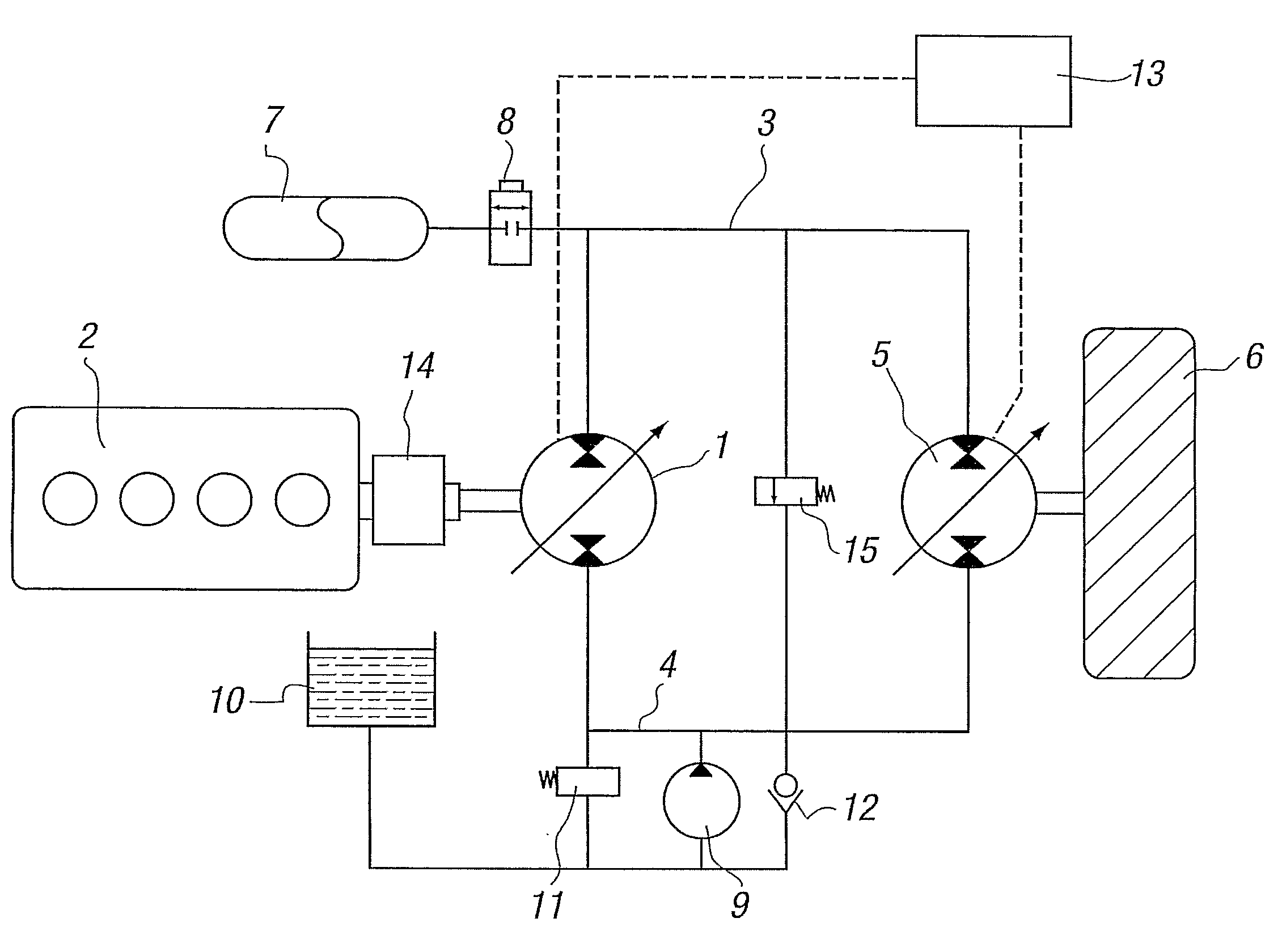
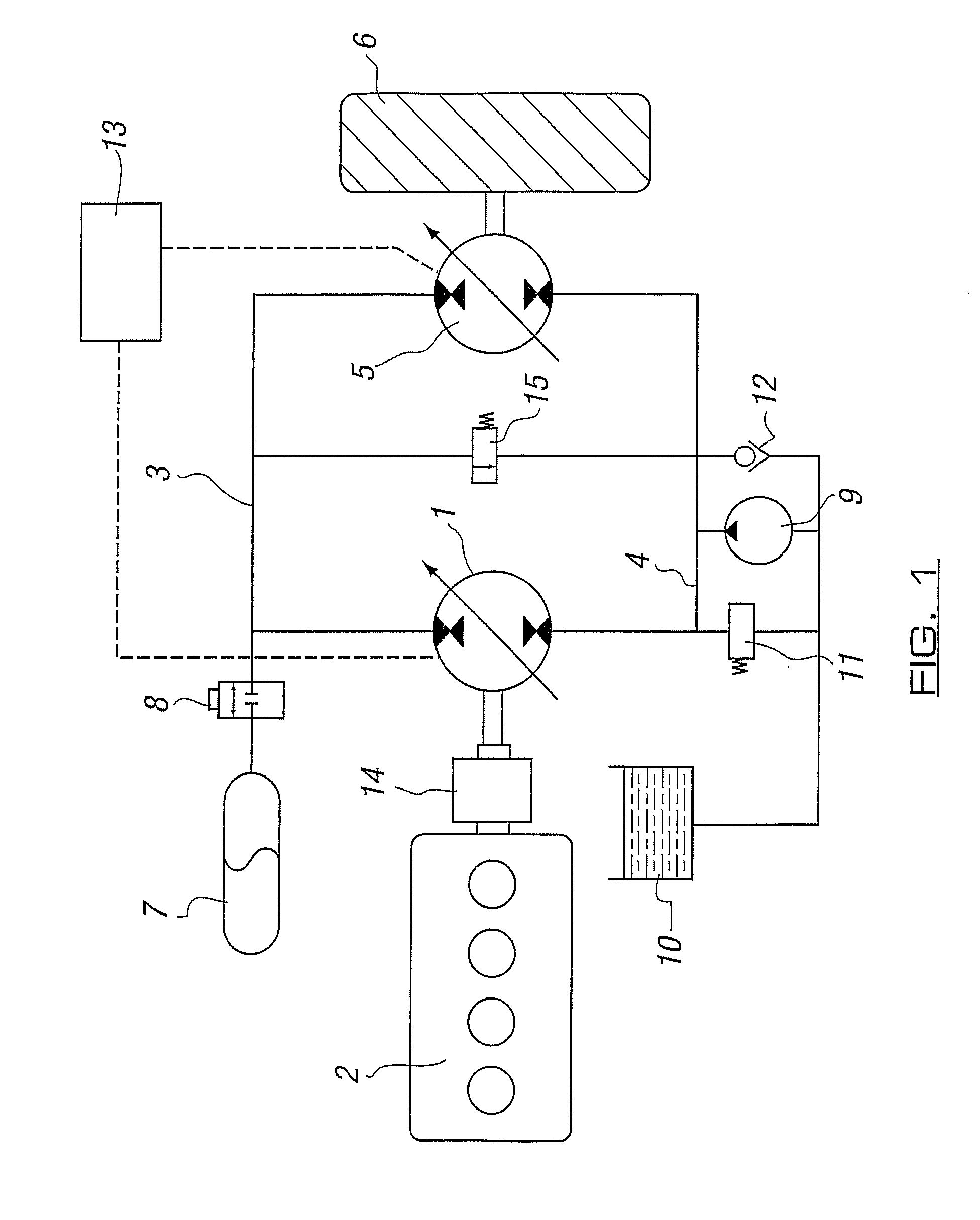
[0024]FIG. 1 shows a possible embodiment of the transmission circuit, different layouts providing the same functionality are not ruled out. The system consists of a first fluid working machine 1 possibly of Digital Displacement™ principle driven by a prime mover 2. The first fluid working machine 1 might be driven directly from the prime mover or through a unit 14, which might contain a clutch or gear drive or both. The high-pressure fluid manifold is connected to a high-pressure fluid line 3. The low-pressure fluid manifold is connected to a low-pressure line 4. A second fluid working machine 5, preferably of Digital Displacement™ principle, is connected to a load 6. Its high-pressure manifold is connected to the fluid line 3 and its low-pressure manifold to a low-pressure fluid line 4. A high-pressure accumulator 7 is connected to the high-pressure fluid line 4 possibly through an on / off valve 8.

[0025]A microprocessor 13 is employed to control the first fluid working machine 1 and...


PUM


Abstract

A variable transmission comprises a first fluid working machine (1) for connection to a prime mover (2), a second fluid working machine (5) for connection to a mechanical load (6) and a fluid system linking the first and second working machines, the fluid system having a high-pressure side (3) and a low-pressure side (4) each connected to both said first and said second fluid working machines (1, 5), a fluid accumulator (7) on the high-pressure side, a means to admit fluid from the reservoir to the low-pressure side and a pressure control valve to maintain the correct pressure in the low-pressure side, wherein the second fluid working machine (5) includes chambers of variable volume having electronically controllable valves such that each of said chambers has pumping, motoring and idling modes of operation, and the second fluid working machine (5) is operable to both source fluid to and sink fluid from each of said high-pressure side (3) and said low-pressure side (4).

Description

FIELD OF THE INVENTION[0001]This invention relates to a hydrostatic infinitely variable transmission. More specifically this invention relates to the type of transmission based on the Digital Displacement™ principal as is described in Patent EP0361927 and in Patent EP0494236. This invention has particular reference to a system which is capable of capturing excess energy, for example during vehicle deceleration, and storing this energy in a hydraulic accumulator, so that it can be reused later in order to improve economy and enhance driveability. The invention specifically refers to such a system operating without the need for a large accumulator on the low-pressure side of the system but still providing appropriate charge pressure to the fluid working machines at times of high operational speed in order to avoid inlet cavitation. This invention has particular reference to a vehicle propulsion application, but its use in other hydrostatic transmission applications is not ruled out. I...

Claims


Application Information

Patent Timeline
IPC IPC(8): G06F19/00F16H61/40F16H61/4026F16H61/4096F16H61/448
CPCB60K6/12Y02T10/6208F04B49/065F15B1/024F15B7/008F15B21/14F15B2211/20523F15B2211/20546F15B2211/20561F15B2211/20569F15B2211/212F15B2211/7058F15B2211/88F16H61/4026F16H61/4096F16H61/448F04B7/0076Y02T10/62F04B7/00F04B49/06F15B1/02F16H61/40
Inventor STEIN, UWE BERNHARD PASCALFIELDING, MICHAEL RICHARD
Owner ARTEMIS INTELLIGENT POWER
Why Eureka
Try Eureka