Heated Hot-Film Air-Mass Sensor

a sensor and hot film technology, applied in the direction of electrical control, instruments, machines/engines, etc., can solve the problems of contaminating the sensor chip, such as with oil, and affecting the measurement accuracy of the measurement, so as to minimize the contamination of the surface of the sensor chip and optimize the displacement process

Active Publication Date: 2009-08-27
ROBERT BOSCH GMBH
View PDF14 Cites 29 Cited by
  • Summary
  • Abstract
  • Description
  • Claims
  • Application Information

AI Technical Summary

Benefits of technology

[0016]Furthermore, because of the heating of the entire sensor chip, the thermal gradient turbulences, that were mentioned, at the transition between a heated surface and a cold surface in the surrounding flow medium are displaced from the surface of the sensor chip all the way to the edge of the sensor chip. Since oil contamination, particularly by oil vapors and oil mists diffusing into a bypass, which may appear in the region of these thermogradient turbulences, the zone of these thermo-gradient turbulences, and thus the zone of maximum pollution is pushed away from the chip surface to the chip carrier, by the embodiment of the hot-film air-mass sensor according to the present invention. Contamination of the surface of the sensor chip is minimized too, thereby. The sensor diaphragm is hardly hit any more by oil droplets and therefore remains clean, and because of this, a sensor drift is largely avoided during operation.
[0017]The hot-film air-mass sensor, according to the present invention, may be operated to the extent that at least one additional heating element essentially heats the sensor chip continuously during the operation of the hot-film air-mass sensor. Even the adaptation of the heating to various operating states of the internal combustion engine is conceivable, in particular, for example, in operating states in which an aggravated oil contamination is to be expected, stronger heating of the sensor chip taking place.

Problems solved by technology

One difficulty with this type of sensor, for example, from DE 101 11 840 C2 is that contamination of the sensor chip, such as with oil, may frequently occur.
Even in the operation of the internal combustion engine, oil may deposit on the sensor chip and especially on the sensor diaphragm, in this instance.
This oil deposit may lead to an undesired effect on the measuring signal of the sensor chip, especially since an oil film on the surface of the sensor chip has an effect on the thermal conductivity of the surface, which leads to a corruption of the measuring signals.
This oil contamination appears particularly during, or shortly after the shutting down of the internal combustion engine, for instance, of a Diesel engine.
Moreover, on the surface of the sensor chip, in addition, at least one additional heater is situated, which may be heated electrically in such a way that, in the region of the additional heater, thermogradient turbulences are formed, which lead to the depositing of contamination in the region of the additional heater, out of the way of the region of the sensor region.
However, this device from the related art has various disadvantages.
A substantial disadvantage is that, in DE 101 11 840 C2, the additional heater is situated directly near or even on the sensor diaphragm.
In the case of heavy oil loading, this adjacent positioning of additional heater and sensor diaphragm can, however, lead to oil droplets flowing back onto the sensor diaphragm, and can consequently, in turn, lead to contamination of the sensor diaphragm, and to a change in thermal conductivity connected therewith, and consequently to a signal drift.
Furthermore, one disadvantage of the situation shown in DE 101 11 840 C2 is the so-called Marangoni effect, which is the development of different surface tensions at different temperatures.
Consequently, the device in DE 101 11 840 C2 may even have the disadvantage that oil droplets on the surface of the sensor chip are pushed from the additional heater to the sensor diaphragm, and thus the contamination of the sensor diaphragm is even increased, instead of lowered.
An additional disadvantage of the device from the related art is that the main contamination by oil, as explained above, appears at, or shortly after the shutting down of the internal combustion engine, since, at that time, oil mists diffuse through the intake tract and the bypass all the way to the hot-film air-mass sensor, and contaminate it.
The devices known from the related art thus have the disadvantage that, immediately after shutting down the internal combustion engine, the hot-film air-mass sensor is strongly contaminated with oil.

Method used


Image

  • Heated Hot-Film Air-Mass Sensor
  • Heated Hot-Film Air-Mass Sensor
  • Heated Hot-Film Air-Mass Sensor

Examples


Embodiment Construction

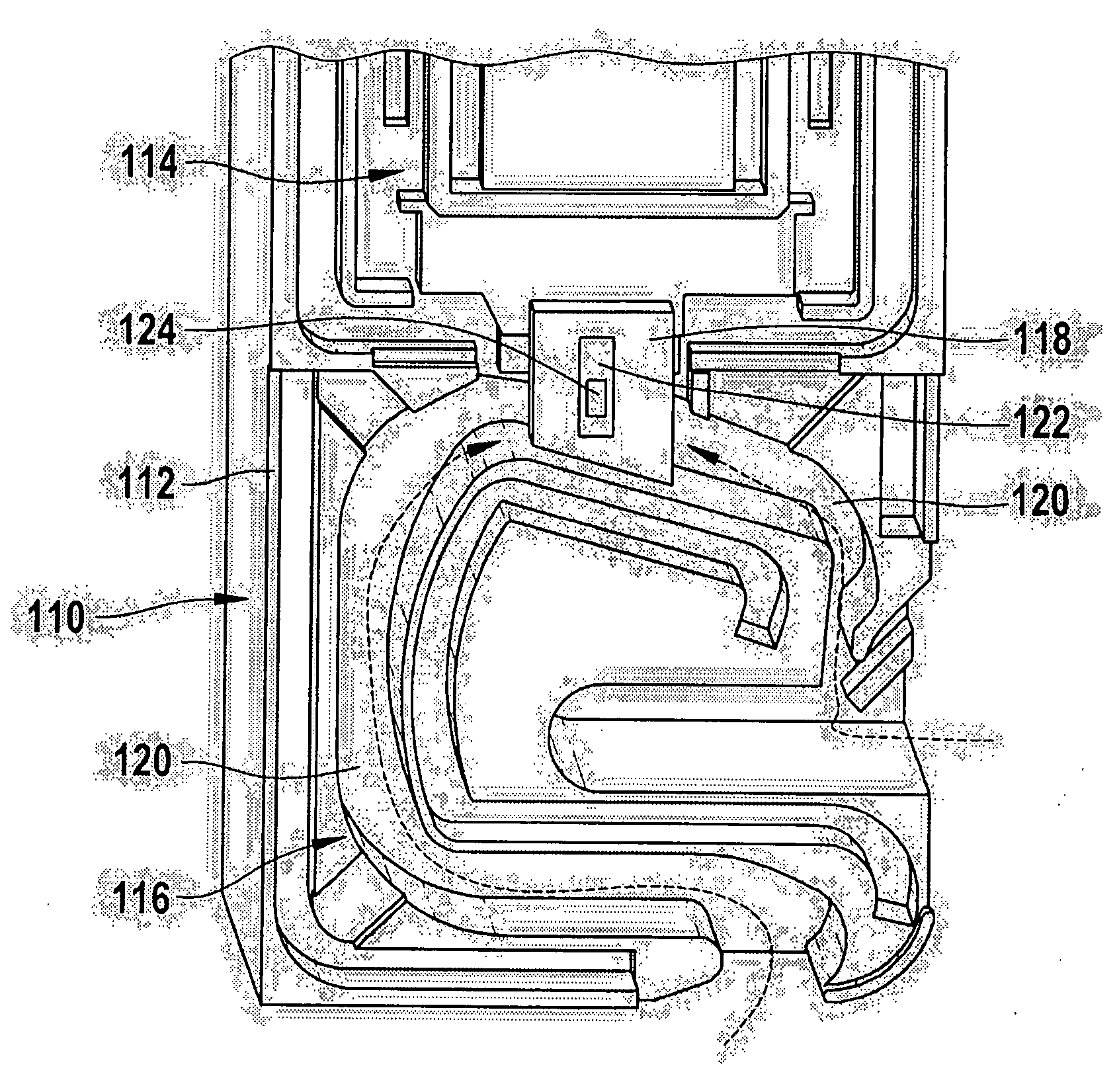
[0030]A hot-film air-mass sensor 110 is shown in FIG. 1, in a view from above. Hot-film air-mass sensor 110 has a housing 112, which may be developed, for instance, as an injection molded component. Housing 112 has an electronics area 114 and a channel region 116. Electronic area 114 essentially has a recess for accommodating a sensor housing which, however, is not shown in FIG. 1, to keep things simple. Formed onto the sensor housing is a chip carrier 118 developed as sensor nose 118 which extends into a bypass channel 120 that is let into channel region 116 of housing 112. The entire hot-film air-mass sensor 110 is built into an intake tract of an internal combustion engine in such a way that air from the intake tract is able to flow out of the intake tract through bypass channel 120 to chip carrier 118.

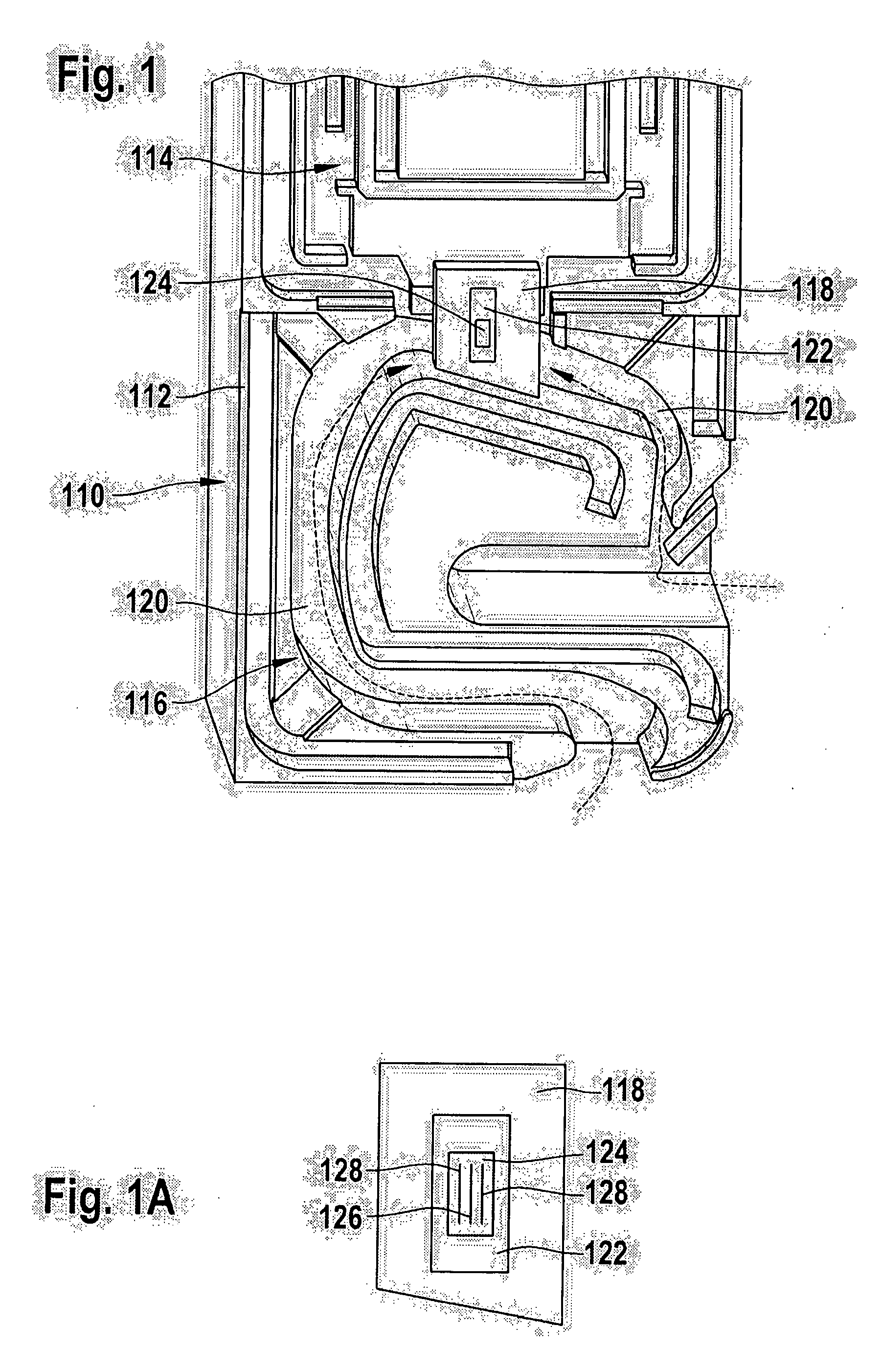
[0031]A sensor chip 122 is let into chip carrier 118, and it has an active area in the form of a diaphragm 124. Sensor chip 122 is developed, for instance, according to the device ...


PUM

PropertyMeasurementUnit
temperaturesaaaaaaaaaa
temperatureaaaaaaaaaa

Abstract

To determine air mass flows, especially for controlling internal combustion engines, a hot-film air-mass sensor is provided, which may be used especially for sensing air mass flows in the intake tract of an internal combustion engine. The hot-film air-mass sensor has a sensor chip having a sensor frame and a sensor diaphragm having at least one heating element and at least two temperature sensors. Furthermore, the hot-film air-mass sensor has a chip carrier for mounting the sensor chip, as well as at least one additional heating element. The sensor chip is able to be heated up using the at least one additional heating element, which is inserted into the chip carrier. Compared to the usual devices, the hot-film air-mass sensor has a lower susceptibility to contamination, especially by oil films.

Description

FIELD OF THE INVENTION[0001]The present invention relates to a hot-film air-mass sensor, particularly for measuring air-mass flows in the intake tract of an internal combustion engine. The present invention particularly relates to a hot-film air-mass sensor having at least one additional heating element for heating up a sensor chip. The present invention also relates to a method for air-mass sensing in the intake tract of an internal combustion engine using a hot-film air-mass sensor according to the present invention, as well as a method for producing a hot-film air-mass sensor.BACKGROUND INFORMATION[0002]In many processes, for instance, in the field of industrial processing engineering, chemistry or machine construction, a gas mass, especially an air mass, has to be supplied in a specific manner. Among these are especially combustion processes, which run under regulated conditions. In this context, an important example is the combustion of fuel in internal combustion engines of mo...

Claims


Application Information

Patent Timeline
Patent Type & Authority Applications(United States)
IPC IPC(8): G01F1/692H05K3/30
CPCF02D41/187Y10T29/4913G01F1/6983G01F1/692
Inventor RENNINGER, ERHARDHUEFTLE, GERHARDBRUECKNER, JOERGOPITZ, BERNHARDKUENZL, BERNDKONZELMANN, UWEWAGNER, ULRICHMARBERG, HENNINGGMELIN, CHRISTOPHILLIAN, MATTHIAS
Owner ROBERT BOSCH GMBH
Why Eureka
Try Eureka