Wave power system for extracting simultaneously both potential and kinetic energy at variable significant wave heights and periods

a wave power system and potential energy technology, applied in sea energy generation, electrical equipment, engine fuctions, etc., can solve the problems of increasing oil prices, erroneous tendency within, and few devices are conceived to extract both potential energy and kinetic energy of waves

Inactive Publication Date: 2009-08-27
ATILANO ALVARO +5
View PDF10 Cites 9 Cited by
  • Summary
  • Abstract
  • Description
  • Claims
  • Application Information

AI Technical Summary

Benefits of technology

[0018]It is another objective of the present invention to provide a device that may survive harsh weather or high waves.
[0023]In the second configuration of the device, and in order to extract the kinetic energy of waves, flaps or blades are attached to the front leg of the main column or beam at the sea bottom and placed at both sides from this leg, in the case of shallow waters. In the case of deep waters, these flaps or blades are place in front of the main column and attached to the underwater float. These flaps or blades move back when hit by an incoming wave and forth when a wave has passed. In this configuration, the device extract kinetic energy of the wave from the back and forth movement through a system of gears that conduct this back and forth movement to the main column or beam and them to the power take off system in the machine room. The flaps or blades do not move up and down with the float since they are attached to the front leg of the main column or beam at the sea bottom in the case of shallow waters, or to the underwater float in the case of deeper waters. In the second configuration, the flaps or blades for extracting kinetic energy may be place at an optimal horizontal distance from the main column or beam, and therefore, from the float for extracting potential energy of the wave, in order to synchronize the movement of these energy extracting components of the device to make energy extraction more efficient.
[0026]The construction of the device is similar to the construction of buoys and small ships and device is thus very robust.

Problems solved by technology

First, there are global warming issues—carbon dioxide emissions must be reduced in many industrialized countries due to ratification of the Kyoto Convention, and its future successor being discussed in Copenhagen 2009.
Secondly, a dwindling supply of peak oil reserves and growing demand of oil by large nations such as China and India, in addition to growing political tensions in oil producing countries, have increased oil prices tremendously.
Since most developing countries have low energy intensity seas, especially those in the tropical regions, with average wave power levels of 3 to 15 kW / m, the above mentioned issue results in an erroneous tendency within the renewable wave energy technology developers in industrialized countries to believe that the majority tropical countries are not or will not be beneficiaries of this type of technology because of their low energy intensity seas.
Very few devices are conceived to extract both the potential energy and kinetic energy of waves.
Also, these Prior Art systems have no self-oriented capability to position themselves to absorb the maximum amount of energy from waves and thus optimize energy production.

Method used


Image

  • Wave power system for extracting simultaneously both potential and kinetic energy at variable significant wave heights and periods
  • Wave power system for extracting simultaneously both potential and kinetic energy at variable significant wave heights and periods
  • Wave power system for extracting simultaneously both potential and kinetic energy at variable significant wave heights and periods

Examples


Embodiment Construction

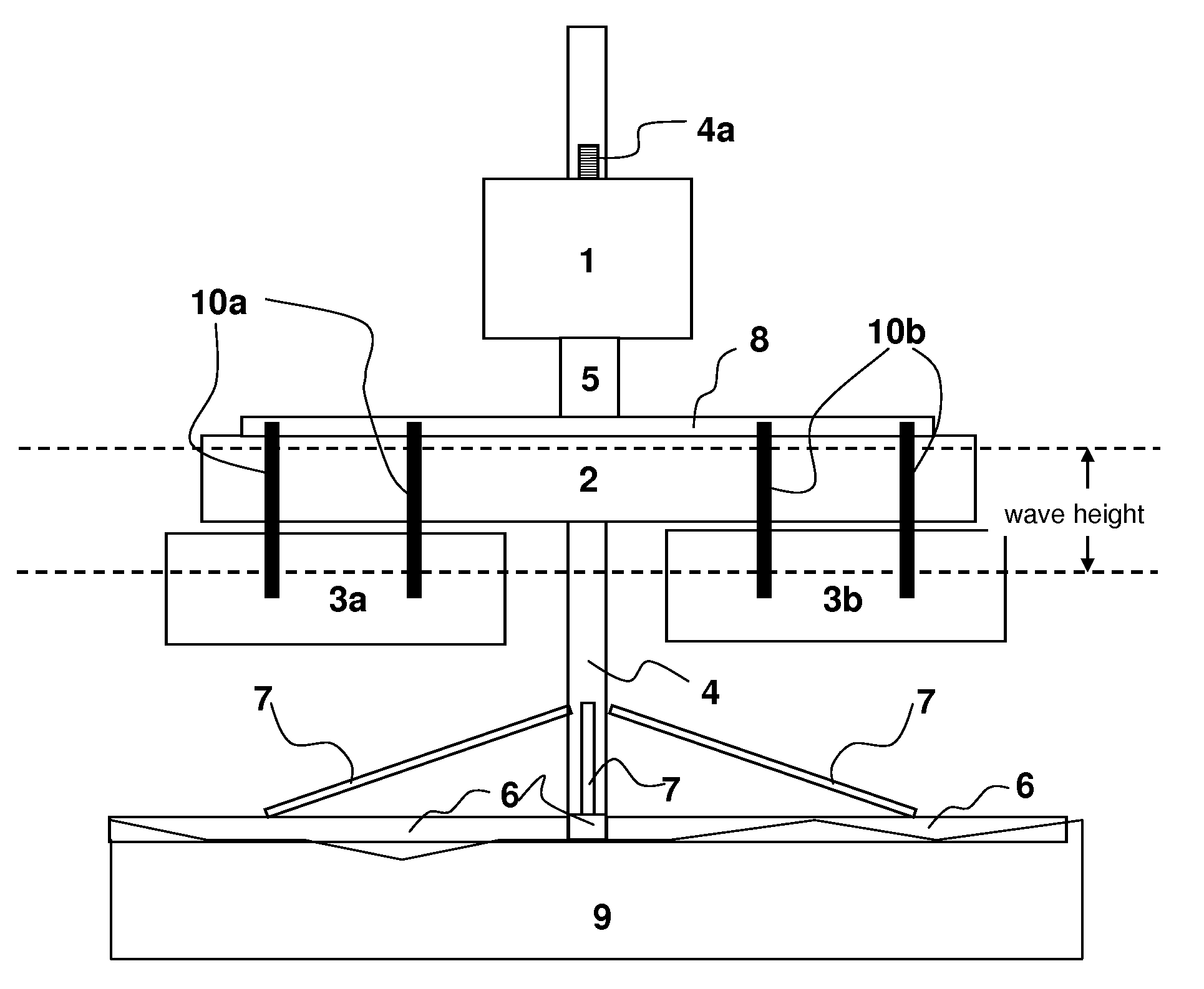
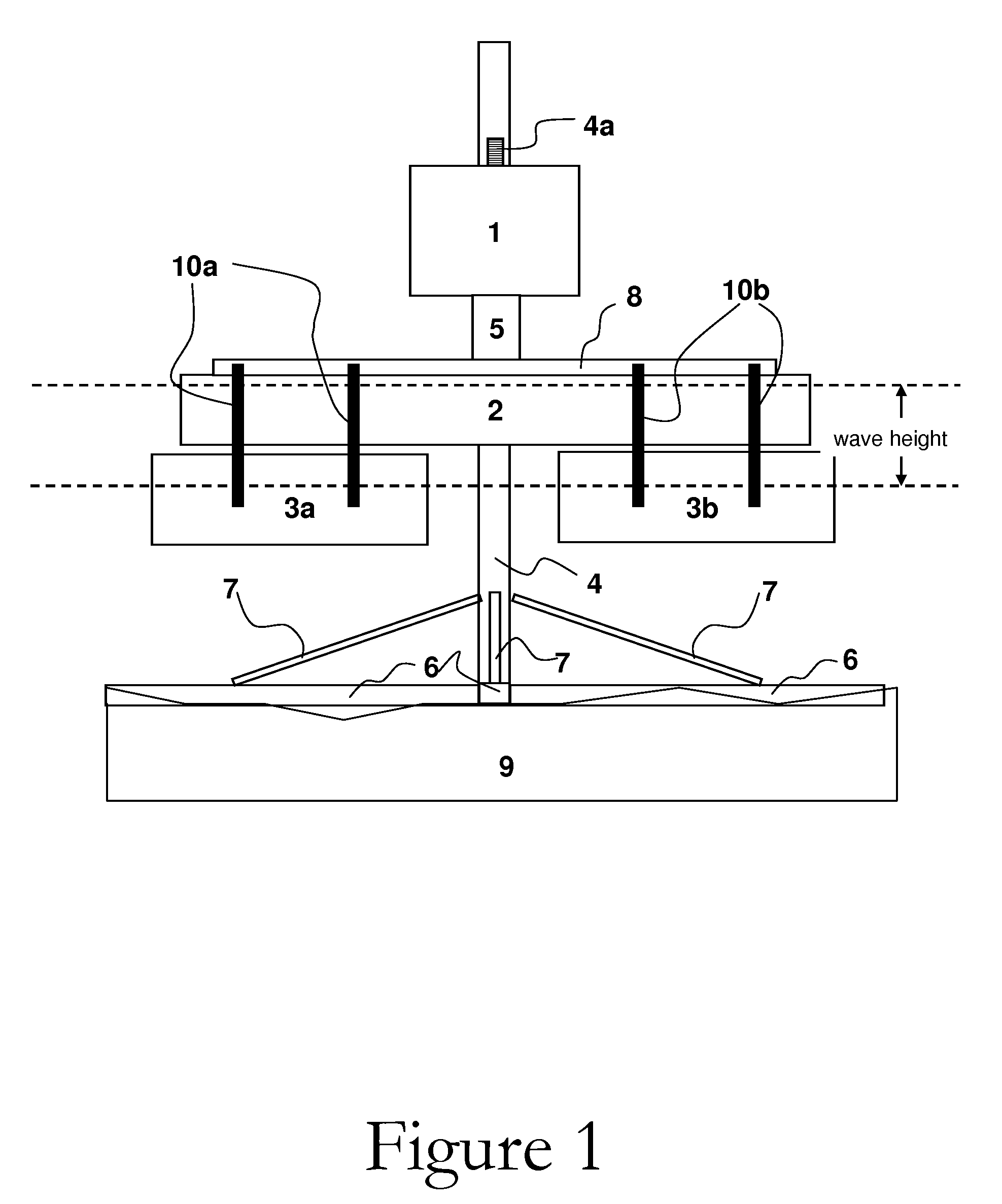
[0050]The following Figures are not to scale. The actual dimension and / or shape of each of the device components may vary. Only important details of the device are shown, however one of ordinary skill in the art can appreciate how the overall device may be constructed, without undue experimentation. The device may be constructed using standard ship building methods and materials or any appropriate materials and methods to allow efficiency and survivability.

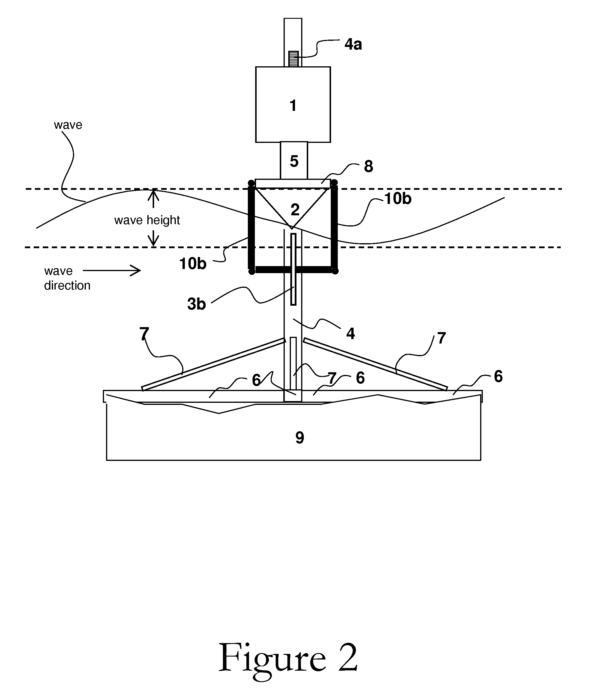
[0051]FIG. 1 is a general front view of the first configuration (flaps or blades hanging from the float frame) of the wave energy converter of the present invention and FIG. 2 is a general side view of the first configuration of the wave energy converter of the present invention. Note the movement and direction of the waves as illustrated in FIG. 2. Referring to FIGS. 1 and 2, the apparatus is composed of a machine room 1 which encloses a power take off system (not shown). Machine room 1 is built in such a manner as to keep water ...


PUM


Abstract

A wave energy conversion system or device includes a float and base on top of which there is a power take-off system. The float, its base and the machine room are inserted in a main column supported by legs and corresponding leg supports on the bottom floor in shallow waters (seas or lakes). In deeper waters, the main column may be supported by column supports attached to an underwater float. The machine room is separated of the float frame through a rotary joint which allows the float and base to rotate in any horizontal direction while maintaining the machine room fixed in the same horizontal direction. The rotary joint separating the float frame and the machine room also allows for the vertical up and down movement when interacting with incoming waves. The distance between the machine room and the float frame is always the same. The device includes flaps or blades for the absorption of kinetic energy derived from the back and forth movement of water generated by waves. The device extracts potential energy of the wave from the up and down movement of the floating structure through a power take-off system in the machine room.

Description

CROSS-REFERENCE TO RELATED APPLICATIONS [0001]The present Application is a Continuation-In-Part, of U.S. patent application Ser. No. 11 / 681,816, filed on Mar. 5, 2007 now U.S. Pat. No. 7,525,214, incorporated herein by reference in its entirety; application Ser. No. 11 / 681,816 in turn claims priority from Provisional U.S. Patent Application Ser. No. 60 / 813,762, filed on Jun. 14, 2006 and also incorporated herein by reference in its entirety.FIELD OF THE INVENTION[0002]The present invention relates to heaving-buoy and oscillating wave surge wave-energy converters. In particular, the present invention is directed toward a physical configuration and mechanical transmission power take-off system for the simultaneous extraction of both the potential and kinetic energy contained in waves of a large range of significant wave heights and wave periods. The invention is a converter that changes both random vertical and horizontal movement of waves into high-speed rotational movement that can ...

Claims


Application Information

Patent Timeline
Patent Type & Authority Applications(United States)
IPC IPC(8): F03B13/18
CPCF03B13/186Y02E10/38F05B2260/503F05B2260/4031Y02E10/30
Inventor ATILANO, ALVAROZARATE, CARTOSZARATE, JAIMEFAVARETTO, MARTOTOVAR, FELIXUZCATEGUL, RAFAEL
Owner ATILANO ALVARO
Why Eureka
Try Eureka