Charge recycling for multi-touch controllers

US20090212642A1Active Publication Date: 2009-08-27APPLE INC

Image

  • Charge recycling for multi-touch controllers
  • Charge recycling for multi-touch controllers
  • Charge recycling for multi-touch controllers

Examples


Embodiment Construction

[0023]In the following description of preferred embodiments, reference is made to the accompanying drawings which form a part hereof, and in which it is shown by way of illustration specific embodiments in which the invention can be practiced. It is to be understood that other embodiments can be used and structural changes can be made without departing from the scope of the embodiments of this invention.

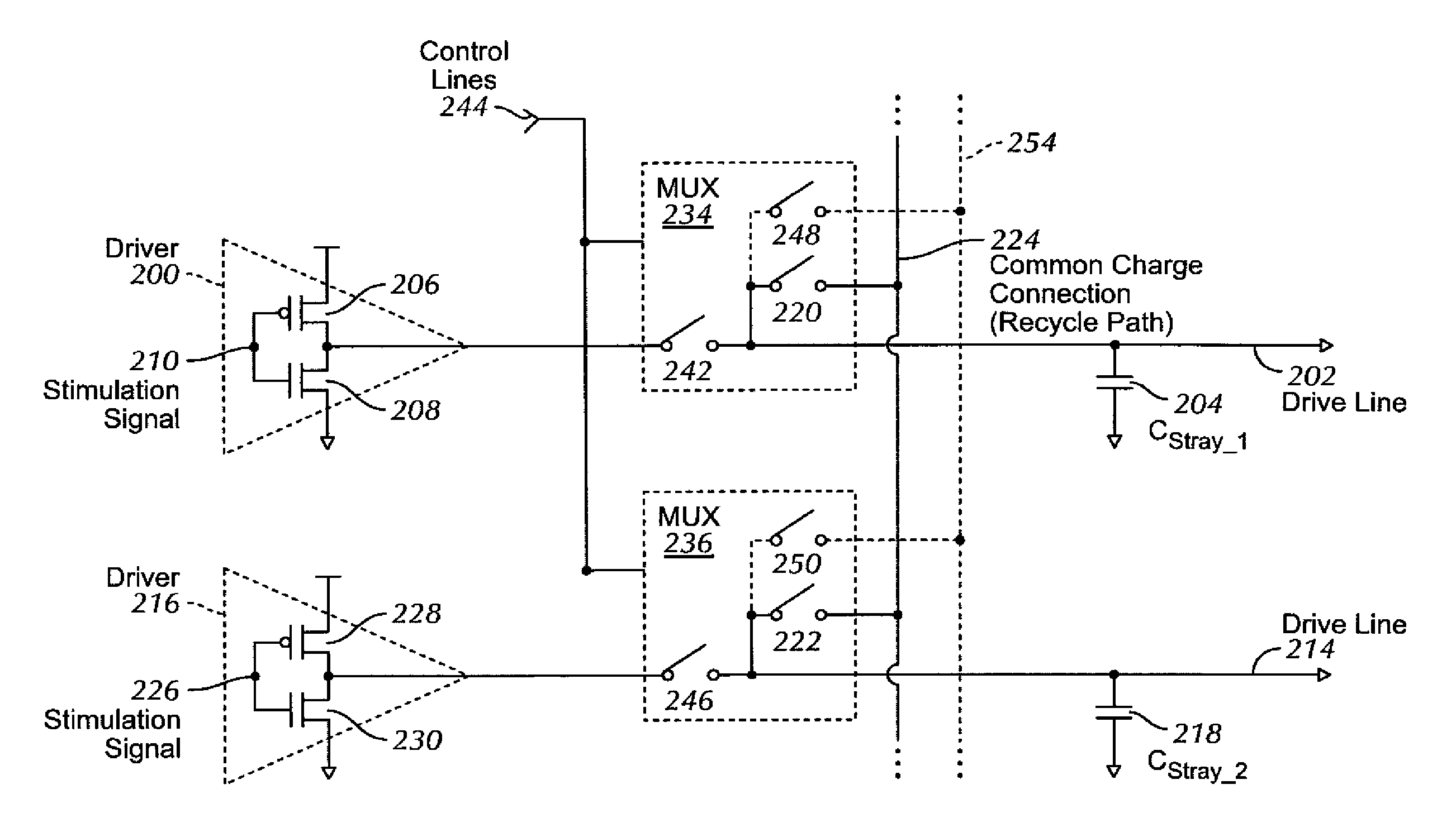
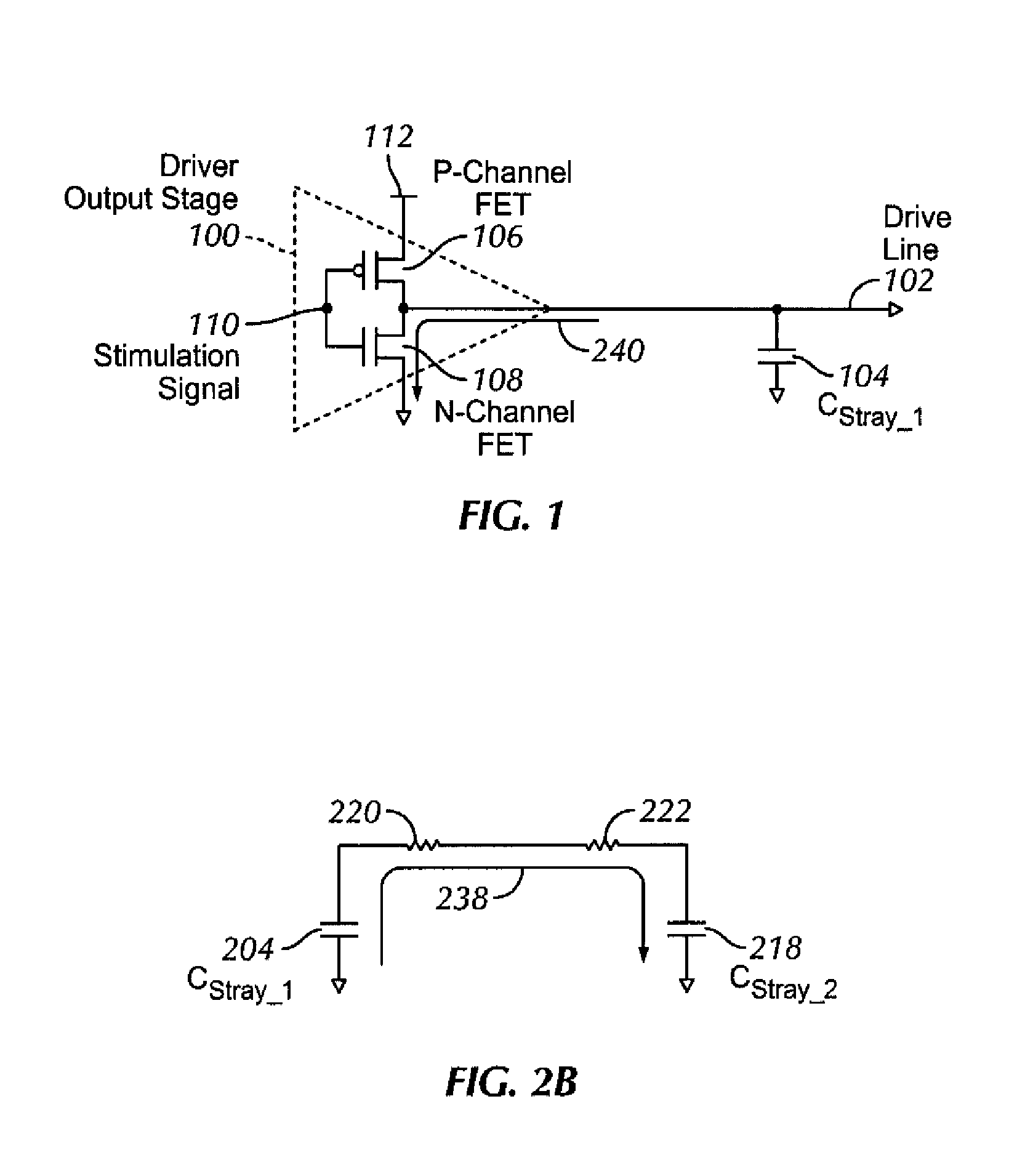
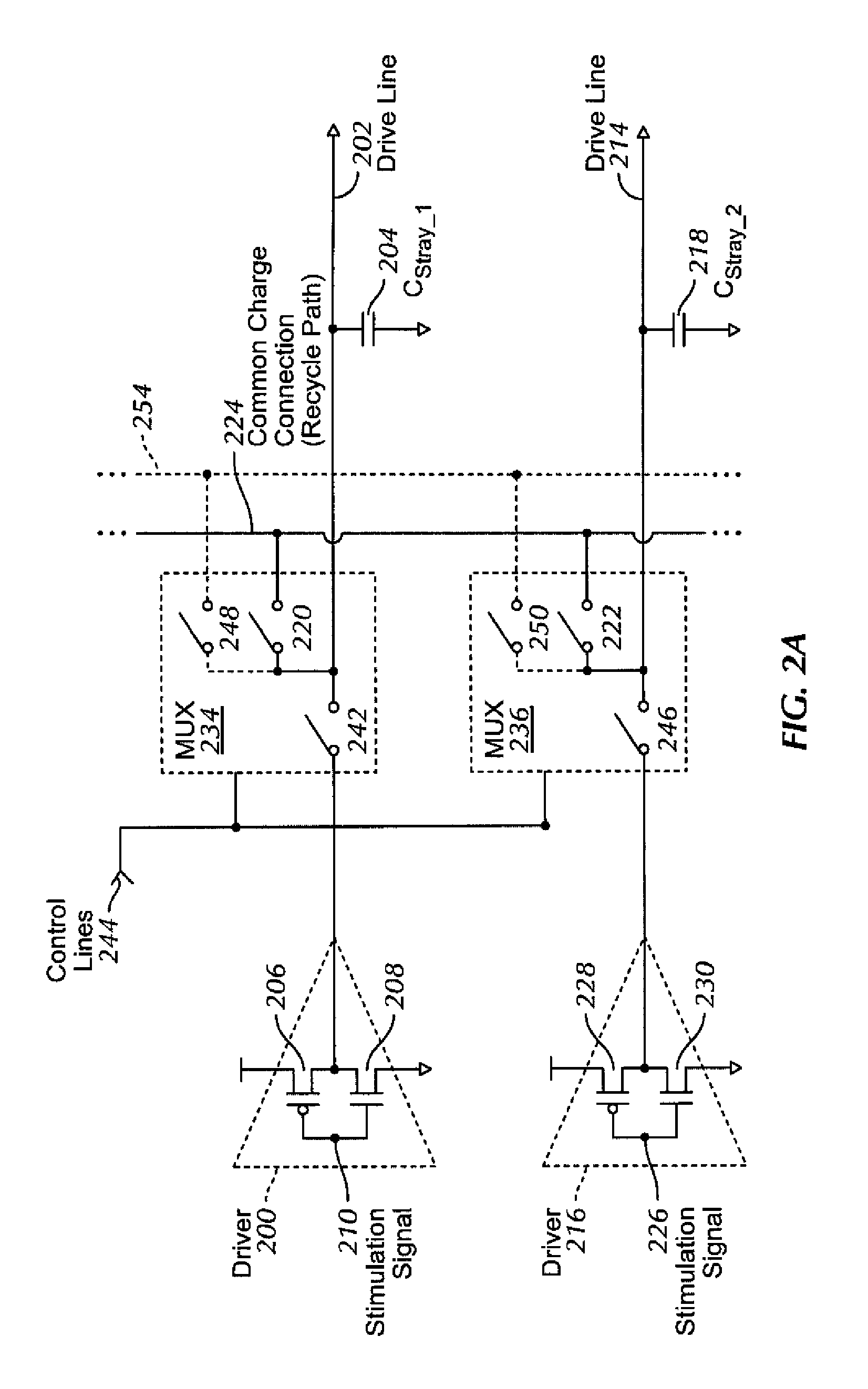
[0024]This relates to the recycling of charge when two or more of the drive lines of a touch sensor panel are being simultaneously stimulated with the in-phase and anti-phase components of a stimulation signal. By discharging the capacitance of a drive line being stimulated with the in-phase component of a stimulation signal into the capacitance of another drive line being stimulated with the anti-phase component of that same stimulation signal, charge is recycled.

[0025]Although some embodiments of this invention may be described herein in terms of mutual capacitance touch sensors, i...


PUM


Abstract

The recycling of charge when two or more of the drive lines of a touch sensor panel are being simultaneously stimulated with the in-phase and anti-phase components of a stimulation signal is disclosed. To perform charge recycling, a discharge path can be selectively formed between drive lines being stimulated with the in-phase and anti-phase components of the stimulation signal. A multiplexer can be coupled to the driver of each drive line and the common discharge path. When charge recycling is to be performed, control logic can configure the multiplexers to isolate the driver and connect the drive lines being stimulated with the in-phase component of the stimulation signal with the drive lines being stimulated with the anti-phase component of the stimulation signal. The capacitance on the charged-up drive lines can then discharge to the capacitance on the discharged drive lines.

Description

FIELD OF THE INVENTION[0001]This relates to touch sensor panels that utilize multiple stimulation frequencies and phases to detect and localize touch events, and more particularly, to the recycling of charge that would otherwise be lost during the discharging of stimulated drive lines.BACKGROUND OF THE INVENTION[0002]Many types of input devices are presently available for performing operations in a computing system, such as buttons or keys, mice, trackballs, joysticks, touch sensor panels, touch screens and the like. Touch screens, in particular, are becoming increasingly popular because of their ease and versatility of operation as well as their declining price. Touch screens can include a touch sensor panel, which can be a clear panel with a touch-sensitive surface, and a display device that can be positioned partially or fully behind the panel so that the touch-sensitive surface can substantially cover the viewable area of the display device. Touch screens can allow a user to per...

Claims


Application Information

Patent Timeline
27 Aug 2009
Publication
US20090212642A1
IPC
H03K3/00
CPC
G06F1/3203; G06F1/3262; H03K19/0019; H03K7/08; G06F3/0416; G06F3/04166
Inventors
KRAH, CHRISTOPH HORST