Liquid Crystal Display Device

a liquid crystal display and display device technology, applied in non-linear optics, instruments, optics, etc., can solve the problems of narrow viewing angle, light leakage, and above cannot meet these requirements, and achieve the effect of high viewing angle and small color shi

Inactive Publication Date: 2009-08-27
FUJIFILM CORP
View PDF6 Cites 11 Cited by
  • Summary
  • Abstract
  • Description
  • Claims
  • Application Information

AI Technical Summary

Benefits of technology

[0021]According to the present invention, a liquid crystal display device assured of a high viewing angle over a wide ambient temperature range and small color shift when displayed in black can be provided.

Problems solved by technology

It has been conventionally a great drawback of the liquid crystal display device that the viewing-angle dependency of the image is large, but in recent years, various high viewing-angle modes differing in the arrayed state of liquid crystal molecules in the liquid crystal cell are put into practical use and this allows rapid spreading of the demand for a liquid crystal display device also in the market where a high viewing angle is required, such as television.
However, a liquid crystal display device for a large-screen television expected to be seen from various angles imposes severe requirements on the viewing angle dependency, and even the technique above cannot satisfy these requirements.
However, the VA mode has a problem that although the panel may be displayed in almost complete black, light leakage occurs when viewed from an oblique direction and the viewing angle is narrowed.
These techniques produce improvements in view of wide viewing angle and black display, but Δnd of the liquid crystal cell changes at high temperatures and because of this reason, the problem that the contrast value decreases in a specific viewing angle direction cannot be solved.
However, the optically anisotropic film described in paragraph 9 of JP-A-2000-155217 (corresponding to U.S. Pat. No. 6,294,231) is an optically anisotropic film having specific physical properties obtained by mixing a polymer and a liquid crystal compound or a liquid crystal composition and lacks production suitability as a retardation film, because the liquid crystal compound or liquid crystal composition is a special composition as being “specified to have a glass transition temperature not more than the lower limit of retardation change of the retardation film required, with the isotropic phase transition temperature being selected to match the temperature dependency of Δnd of the liquid crystal cell used in combination”.
Also, even if this optically anisotropic film may respond to the change of Δnd associated with the temperature change of the liquid crystal cell, there still remains a problem that the color shift with respect to the wavelength fluctuation cannot be improved.

Method used


Image

  • Liquid Crystal Display Device
  • Liquid Crystal Display Device
  • Liquid Crystal Display Device

Examples


example 1

[Production of Viewing-Side Polarizing Plate Protective Films (F-1 to F-8)]

(1) Production of F-1

[0238]Respective components shown in Table 1 below were mixed to prepare a cellulose acylate solution. This cellulose acylate solution was cast on a metal support, and the obtained web was separated from the band support to produce Transparent Film F-1. The film thickness was 70 μm.

TABLE 1ComponentCellulose acylate with an acetyl100parts by weightsubstitution degree of 2.87Triphenyl phosphate5parts by weightBiphenyl phosphate3parts by weightRetardation Controlling Agent A6parts by weightRetardation Controlling Agent B5parts by weightMethylene chloride544parts by weightMethanol81parts by weightMatting agent (AEROSIL R972,0.05parts by weightproduced by Nippon Aerosil Co.,Ltd.)(Retardation Controlling Agent A)(Retardation Controlling Agent B)

(Evaluation of Optical Performance)

[0239]The Re retardation value and Rth retardation value at wavelengths of 450 nm, 550 nm and 630 nm were measured a...

example 2

[Production of Backlight-Side Polarizing Plate Protective Films (R-1 and R-2)]

(1) Production of R-1

[0248]Respective components shown in Table 6 below were mixed to prepare a cellulose acylate solution. This cellulose acylate solution was cast on a metal support. The film stripped off from the metal support in a state of the residual solvent amount being from 25 to 35 mass % was 3% stretched in the longitudinally direction within the section from stripping to a tenter under the conditions of a stretching temperature of about Tg−5° C. to Tg+5° C. and then stretched in the width direction at a stretch ratio of 32% by using a tenter and immediately after the transverse stretching, the film was shrunk in the width direction at a ratio of 7% and then removed from the tenter to prepare a cellulose acylate film. The film thickness was 80 μm.

TABLE 6ComponentCellulose acylate with an acetyl100parts by weightsubstitution degree of 2.81Triphenyl phosphate7.8parts by weightBiphenyl phosphate3.9...

example 3

[0255]A 80 μm-thick polyvinyl alcohol (PVA) film was dyed by dipping it in an aqueous potassium iodide solution having a potassium iodide concentration of 2 mass % at 30° C. for 60 seconds, then longitudinally stretched to 5 times the original length while dipping the film in an aqueous boric acid solution having a boric acid concentration of 4 mass % for 60 seconds, and dried at 50° C. for 4 minutes to obtain Polarizer A of 20 μm in thickness.

[0256]Also, a 80 μm-thick polyvinyl alcohol (PVA) film was dyed by dipping it in an aqueous potassium iodide solution having a potassium iodide concentration of 12 mass % at 30° C. for 60 seconds, then longitudinally stretched to 5 times the original length while dipping the film in an aqueous boric acid solution having a boric acid concentration of 4 mass % for 60 seconds, and dried at 50° C. for 4 minutes to obtain Polarizer B of 20 μm in thickness.

[0257]The protective films produced in Examples 1 and 2 shown in Tables 5 and 8 and a commerci...


PUM

PropertyMeasurementUnit
wavelengthaaaaaaaaaa
temperatureaaaaaaaaaa
thicknessaaaaaaaaaa

Abstract

A liquid crystal display device includes: a liquid crystal cell; and a pair of polarizing plates sandwiching the liquid crystal cell and each including a polarizer and a protective film provided on a side of the liquid crystal cell, in which transmission axes of the pair of polarizing plates are orthogonally arranged, wherein Rth(λ) of at least one of the protective films provided on the liquid crystal cell side of the polarizing plates has negative characteristics for ambient temperature, in which Rth(λ) represents a retardation in a thickness direction measured at a wavelength of λ nm.

Description

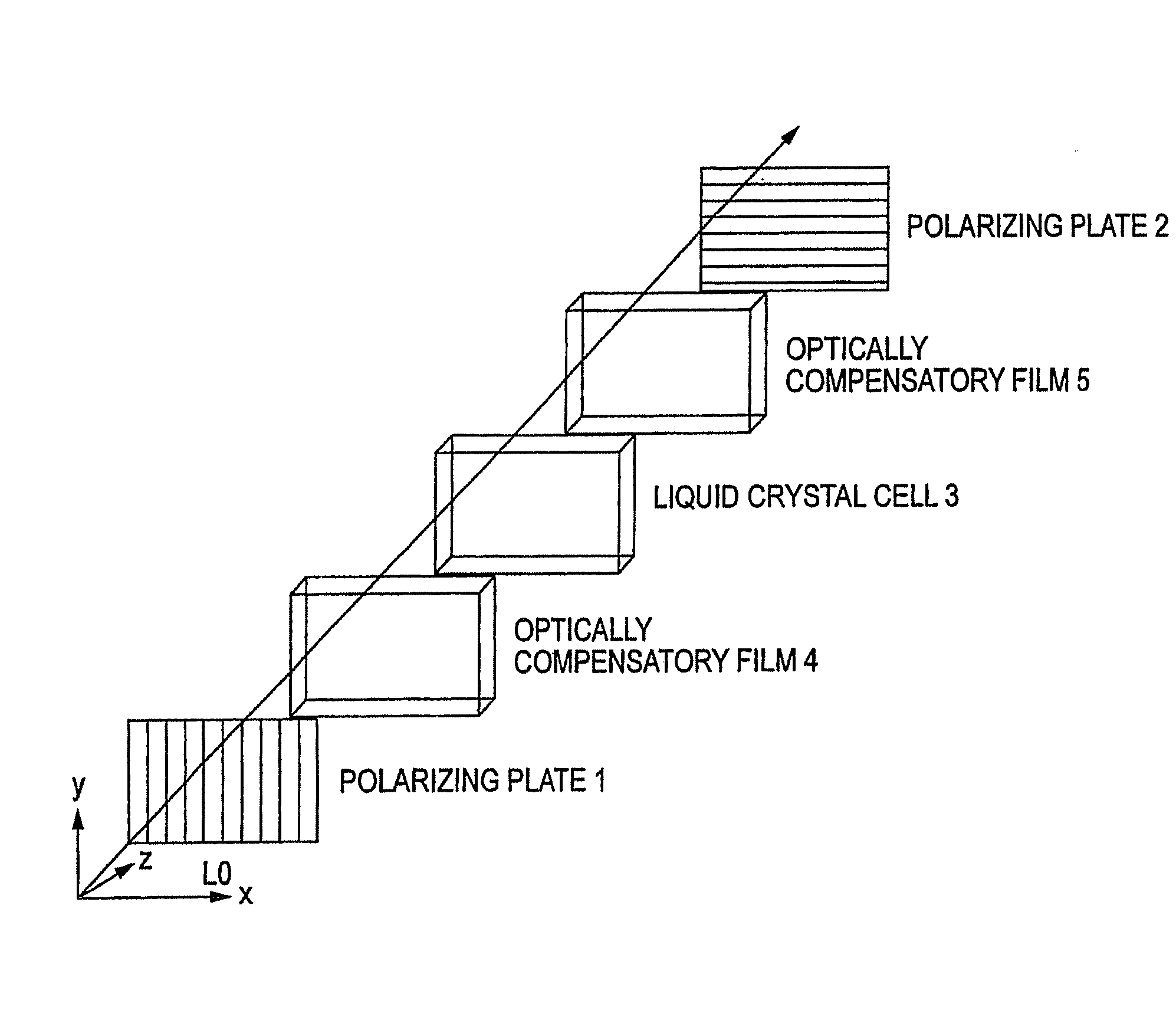
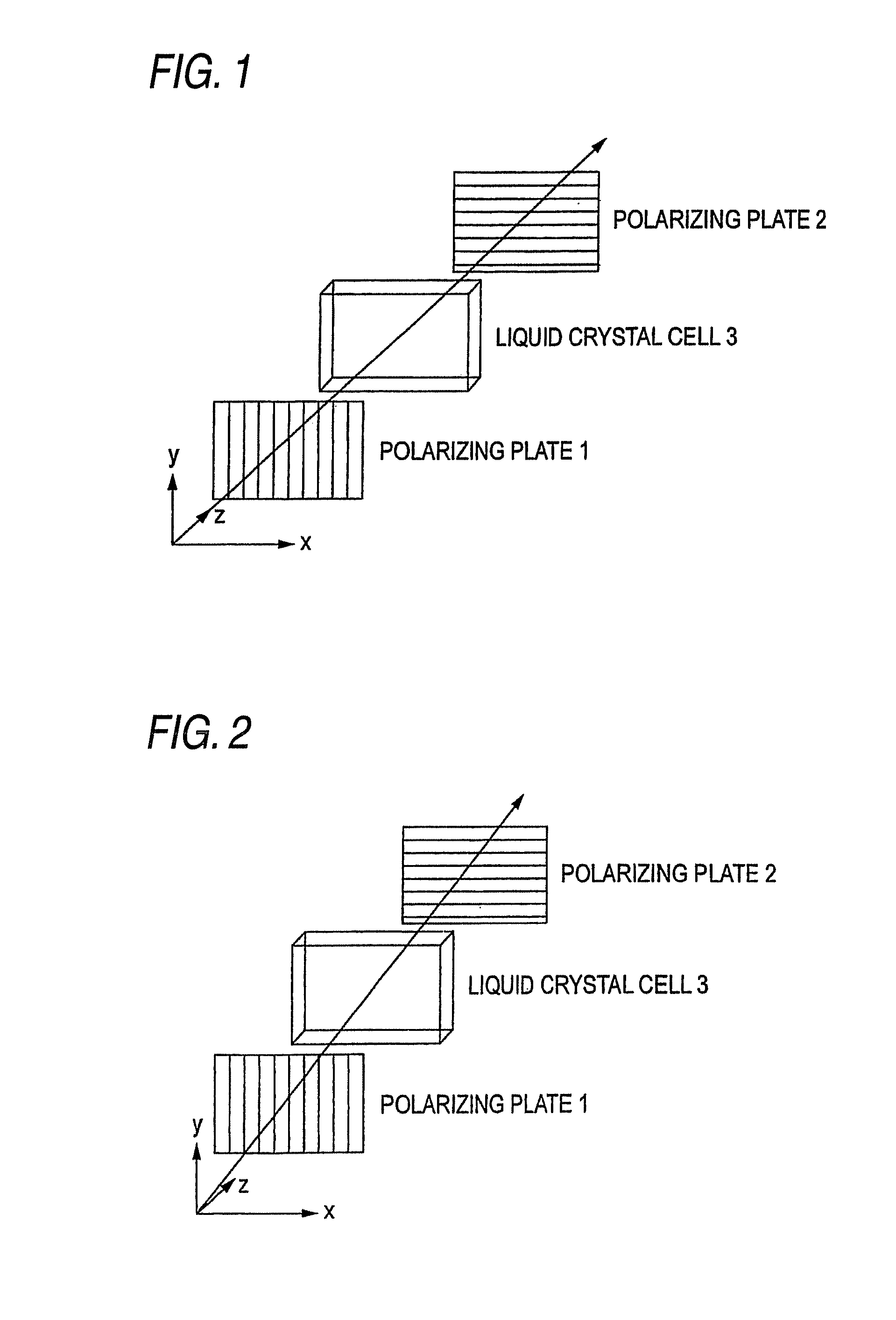
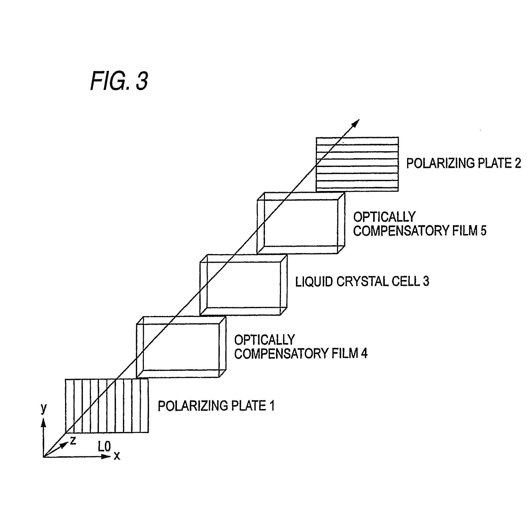
CROSS-REFERENCE TO RELATED APPLICATIONS[0001]This application claims the benefit of Japanese Patent Application JP 2008-040508, filed Feb. 21, 2008, the entire content of which is hereby incorporated by reference, the same as if set forth at length.FIELD OF THE INVENTION[0002]The present invention relates to a liquid crystal display device, more specifically, a liquid crystal display device assured of a high viewing angle over a wide ambient temperature range and small color shift when displayed in black.BACKGROUND OF THE INVENTION[0003]A liquid crystal display device is increasingly used year by year as a space-saving, less power-consuming image display device. It has been conventionally a great drawback of the liquid crystal display device that the viewing-angle dependency of the image is large, but in recent years, various high viewing-angle modes differing in the arrayed state of liquid crystal molecules in the liquid crystal cell are put into practical use and this allows rapid...

Claims


Application Information

Patent Timeline
Patent Type & Authority Applications(United States)
IPC IPC(8): G02F1/13363
CPCG02F1/133528G02F2001/133637G02F1/133634G02F1/133637
Inventor HISAKADO, YOSHIAKIFURUKAWA, HIROMICHI
Owner FUJIFILM CORP
Why Eureka
Try Eureka