Fuel cell, fuel cell stack, and method for manufacturing fuel cell

a fuel cell and stack technology, applied in the direction of cell components, final product manufacturing, sustainable manufacturing/processing, etc., can solve the problems of increasing the manufacturing cost of the fuel cell and consequently the fuel cell stack, the possibility of a product leaking from the end surface of the electrolyte membrane, and the complexity of operation, so as to achieve hardly degraded sealability and adhesiveness, and high sealability and adhesiveness.

Active Publication Date: 2009-08-27
SUMITOMO RIKO CO LTD
View PDF21 Cites 10 Cited by
  • Summary
  • Abstract
  • Description
  • Claims
  • Application Information

AI Technical Summary

Benefits of technology

[0056]The first intermediate portion of the first cross-linking adhesive member is arranged between the pair of frames. In addition, the pair of frames are subjected to cross-linking adhesion with the first cross-linking adhesive member. Therefore, the fuel cell stack of the present aspect has high sealability and adhesiveness between the pair of frames and the first cross-linking adhesive member.
[0057]The first cross-linking adhesive member is formed of rubber. It is therefore less likely that the first cross-linking adhesive member separates from the outer periphery portion of the electrolyte membrane due to heat, unlike in the thermoplastic resin of the annular ribbon of the fuel cell of the Japanese Patent Application Publication No. JP-A-2007-157420 mentioned above.
[0058]The first cross-linking adhesive member is formed of rubber, and therefore is highly water-repellent. Thus, moisture hardly reaches the adhesion boundary surface between the outer periphery portion of the electrolyte membrane and the first cross-linking adhesive member and the adhesion boundary surface between the pair of frames and the first cross-linking adhesive member. That is, the sealability and the adhesiveness are hardly degraded between the outer periphery portion of the electrolyte membrane and the first cross-linking adhesive member and between the pair of frames and the first cross-linking adhesive member.
[0060](11) In order to solve the problems described above, according to an eleventh aspect of the present invention, a method for manufacturing a fuel cell includes the steps of: arranging a sub-assembly in a cavity of a mold, the sub-assembly including an MEA having an electrolyte membrane and a pair of electrodes arranged on both sides of the electrolyte membrane in a thickness direction, a pair of frames having a frame shape and holding an outer periphery portion of the electrolyte membrane, a pair of gas diffusion layers arranged inside the pair of frames and on both sides of the MEA in the thickness direction, and a first cross-linking adhesive member formed of uncross-linked rubber, which includes a membrane accommodating portion having an indented shape for accommodating an outer periphery portion of the electrolyte membrane and a first intermediate portion interposed between the pair of frames; and integrating the first cross-linking adhesive member, the outer periphery portion of the electrolyte membrane, and the pair of frames through cross-linking adhesion in which a gasket raw material is poured in the cavity to form a gasket covering at least a part of the pair of frames and the uncross-linked first cross-linking adhesive member is cross-linked. The term “uncross-linked” refers to a state before the cross-linking is completed. Specifically, not only a state where the cross-linking is yet to be started but also a state where the cross-linking has progressed to some degree is included.
[0061]The method for manufacturing a fuel cell according to the present aspect includes the sub-assembly arrangement step and the integration step. In the sub-assembly arrangement step, the sub-assembly is arranged in the cavity of the mold. The sub-assembly includes the MEA, the pair of frames, the pair of gas diffusion layers, and the first cross-linking adhesive member formed of uncross-linked rubber.
[0062]In the integration step, the gasket raw material is poured in the cavity, whereby the gasket is formed in a predetermined portion of the sub-assembly. In addition, the first cross-linking adhesive member is cross-linked. The first cross-linking adhesive member and the outer periphery portion of the electrolyte membrane are subjected to cross-linking adhesion. In addition, the first cross-linking adhesive member and the frames are subjected to cross-linking adhesion.

Problems solved by technology

Therefore, the possibility of a product leaking from the end surface of the electrolyte membrane is small.
This operation is complicated.
Also, the necessity for this operation leads to an increase in manufacturing cost of the fuel cell and consequently the fuel cell stack.
Therefore, the possibility of a product leaking from the end surface of the electrolyte membrane is small.
Also, there is a possibility of the thermoplastic resin layer of the annular ribbon deforming due to heat.
Thus, the sealability at the end surface of the electrolyte membrane may deteriorate.

Method used


Image

  • Fuel cell, fuel cell stack, and method for manufacturing fuel cell
  • Fuel cell, fuel cell stack, and method for manufacturing fuel cell
  • Fuel cell, fuel cell stack, and method for manufacturing fuel cell

Examples


first embodiment

Fuel Cell Stack

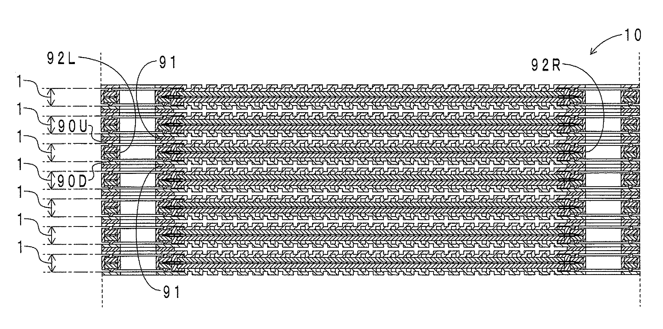
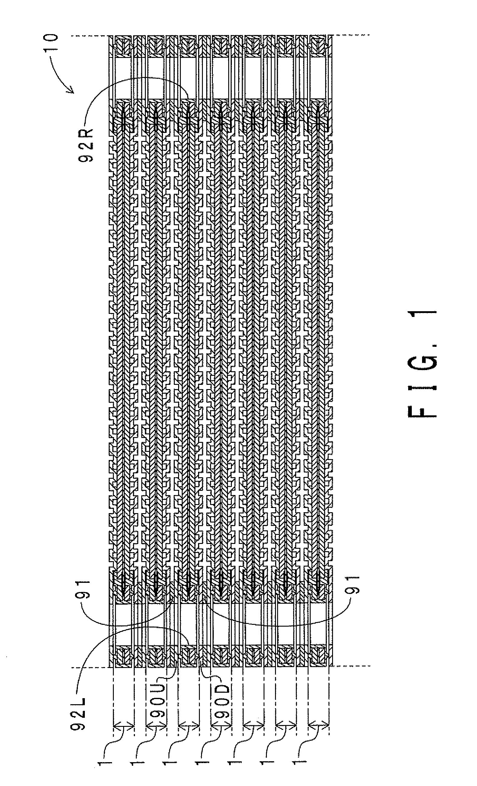
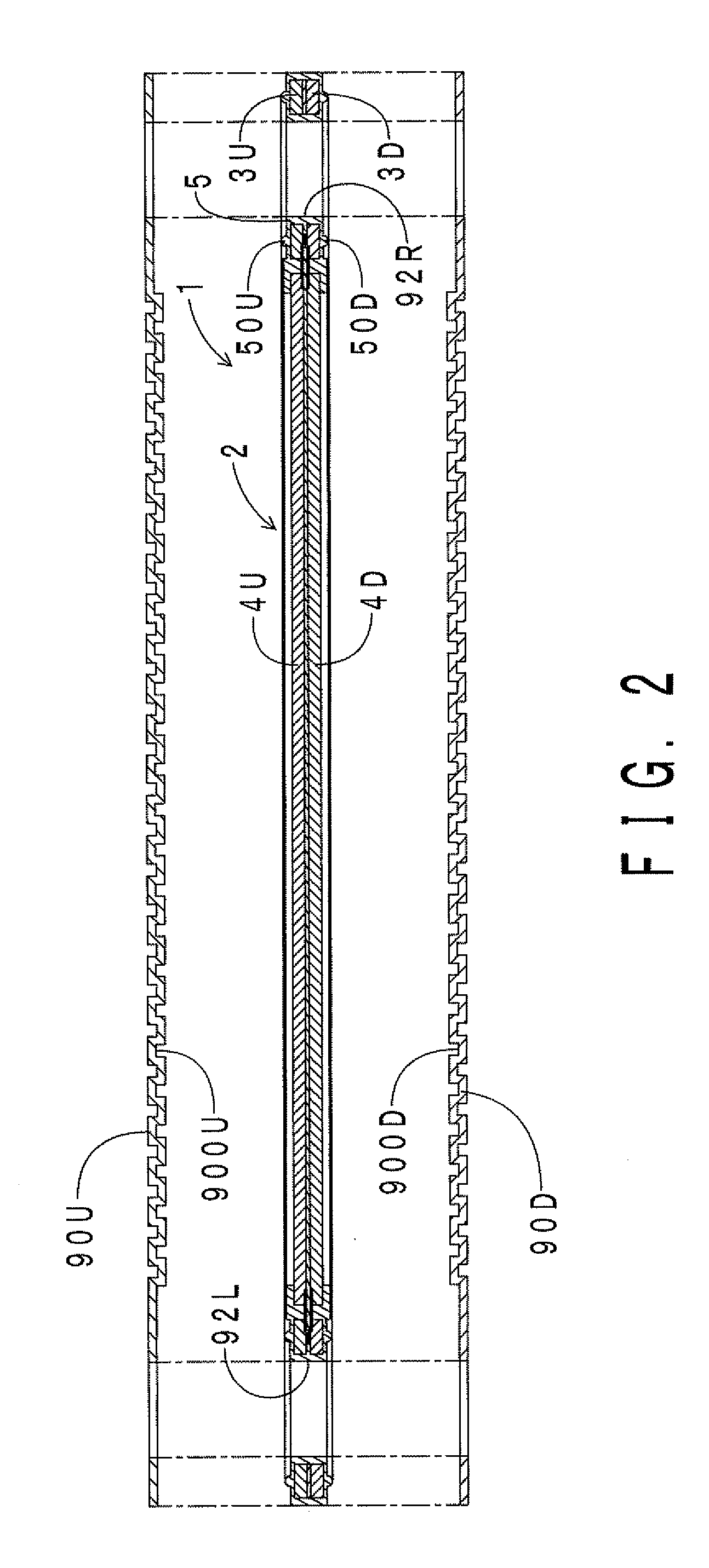
[0095]The configuration of a fuel cell stack of this embodiment will now be described. FIG. 1 shows a partial sectional view of the fuel cell stack of this embodiment in the stacking direction. FIG. 2 shows an exploded view of a fuel cell and a separator of the fuel cell stack.

[0096]As shown in FIGS. 1 and 2, a fuel cell stack 10 of this embodiment includes a fuel cell 1, separators 90U and 90D, and an adhesive member 91. The configuration of the fuel cell 1 will be described later in detail.

[0097]The separator 90U is formed of metal, and has a rectangular thin plate shape with unevenness. Gas flow paths 900U are formed in the separator 90U by the uneven shape. The separator 90U is arranged above an arbitrary fuel cell 1 (specifically, above a gas diffusion layer 4U described later).

[0098]In a similar manner, the separator 90D is formed of metal, and has a rectangular thin plate shape with unevenness. Gas flow paths 900D are formed in the separator 90D by the uneven s...

second embodiment

[0143]A difference of a fuel cell of this embodiment from the fuel cell of the first embodiment is that the volume of the gasket is small. Thus, only the difference will be described here.

[0144]FIG. 8 shows a partial sectional view in the thickness direction of the fuel cell of this embodiment. Note that portions corresponding to those of FIG. 4 are denoted by the same reference symbols. As shown in FIG. 8, gaskets 5U and 5D are not integrated, but are independent from each other. The gasket 5U is arranged on an upper surface of the frame 3U. The gasket 5U has the rib 50U and a base portion 52U. The base portion 52U is secured to the upper surface of the frame 3U. The rib 50U is provided so as to protrude upward from the base portion 52U. In a similar manner, the gasket 5D is arranged on a lower surface of the frame 3D. The gasket 5D has the rib 50D and a base portion 52D. The base portion 52D is secured to the lower surface of the frame 3D. The rib 50D is provided so as to protrude...

third embodiment

[0150]A difference of a fuel cell of this embodiment from the fuel cell of the first embodiment is that the volume of the gasket is small. Another difference is that a second cross-linking adhesive member is arranged between the frame and the gasket. Thus, only the differences will be described here.

[0151]FIG. 10 shows a partial sectional view in the thickness direction of the fuel cell of this embodiment. Note that portions corresponding to those of FIG. 4 are denoted by the same reference symbols. As shown in FIG. 10, the sheet member 6U and a second cross-linking adhesive member 7U are subjected to cross-linking adhesion with a lower surface of the frame 3U and the upper surface of the frame 3U, respectively. The second cross-linking adhesive member 7U is formed of EPDM, and is arranged on the entire upper surface of the frame 3U. In addition, the sheet member 6D and a second cross-linking adhesive member 7D are arranged on an upper surface of the frame 3D and the lower surface o...


PUM

PropertyMeasurementUnit
temperatureaaaaaaaaaa

Abstract

A fuel cell includes a membrane electrode assembly (MEA) having an electrolyte membrane and a pair of electrodes arranged on both sides of the electrolyte membrane in the thickness direction, a pair of frames having a frame shape and holding an outer periphery portion of the electrolyte membrane, a pair of gas diffusion layers arranged inside the pair of frames and on both sides of the MEA in the thickness direction, and a gasket covering at least a part of the pair of frames. The fuel cell further includes a first cross-linking adhesive member formed of rubber which includes a membrane accommodating portion having an indented shape for accommodating the outer periphery portion of the electrolyte membrane and a first intermediate portion interposed between the pair of frames and which is subjected to cross-linking adhesion with the outer periphery portion of the electrolyte membrane and the pair of frames.

Description

INCORPORATION BY REFERENCE[0001]The disclosure of Japanese Patent Application No. 2008-39970 filed on Feb. 21, 2008 including the specification, drawings and abstract is incorporated herein by reference in its entirety.BACKGROUND OF THE INVENTION[0002]1. Field of the Invention[0003]The present invention relates to a fuel cell, a fuel cell stack, and a method for manufacturing a fuel cell.[0004]2. Description of the Related Art[0005]A fuel cell stack has a structure formed by stacking a number of fuel cells. A stack of the number of fuel cells is fastened by end plates arranged on both sides in the stacking direction.[0006]The fuel cell includes a membrane electrode assembly (hereinafter abbreviated as “MEA”). The MEA includes an electrolyte membrane and a pair of electrodes. The pair of electrodes are arranged on both sides of the electrolyte membrane in the thickness direction. One of the pair of electrodes is a fuel electrode, and the other is an oxygen electrode. The fuel electro...

Claims


Application Information

Patent Timeline
Patent Type & Authority Applications(United States)
IPC IPC(8): H01M8/10
CPCH01M8/0273H01M8/0276H01M8/0284Y10T29/4911H01M8/1004H01M2008/1095Y02E60/521H01M8/0286Y02P70/50Y02E60/50H01M8/2483H01M8/242
Inventor TANAHASHI, HIDEAKIISHIOKA, YUTAKAIIZUKA, KAZUTAKAKATO, CHISATO
Owner SUMITOMO RIKO CO LTD
Why Eureka
Try Eureka