Endoscopic aspiration device

a technology of endoscopic aspiration and guide member, which is applied in the field of endoscopic aspiration device, can solve the problems of difficult extraction of valve guide member from valve casing for washing purposes, and achieve the effects of preventing spontaneous dislodgement of valve assembly unit, easy extraction, and convenient disassembly and assembly

Inactive Publication Date: 2009-08-27
FUJIFILM CORP
View PDF3 Cites 127 Cited by
  • Summary
  • Abstract
  • Description
  • Claims
  • Application Information

AI Technical Summary

Benefits of technology

[0012]It is another object of the present invention to provide an endoscopic aspiration device which is adapted to retain a valve assembly unit securely in position within a valve casing free of possibilities of dislodgement from the valve casing while manipulating an endoscope, the valve assembly unit however being easily extractable from the valve casing, for example, when it becomes necessary to wash the valve assembly unit after use.
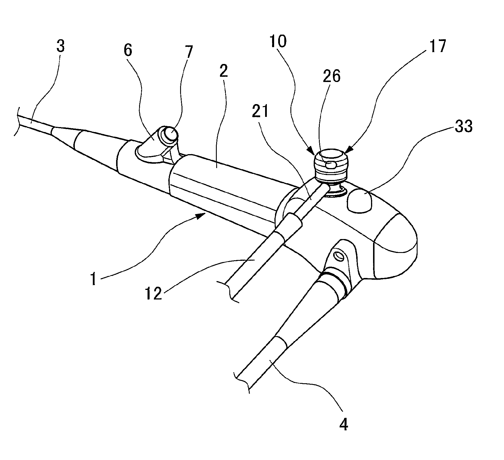
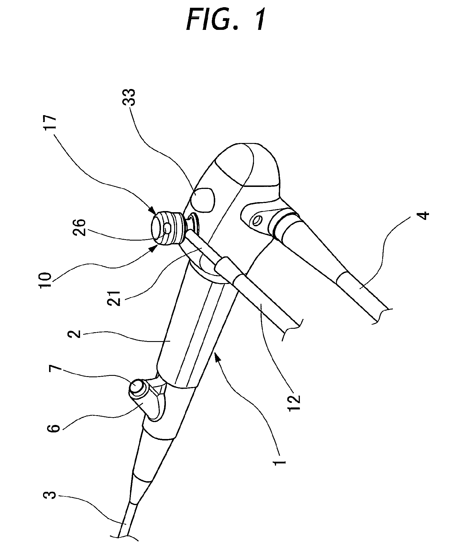
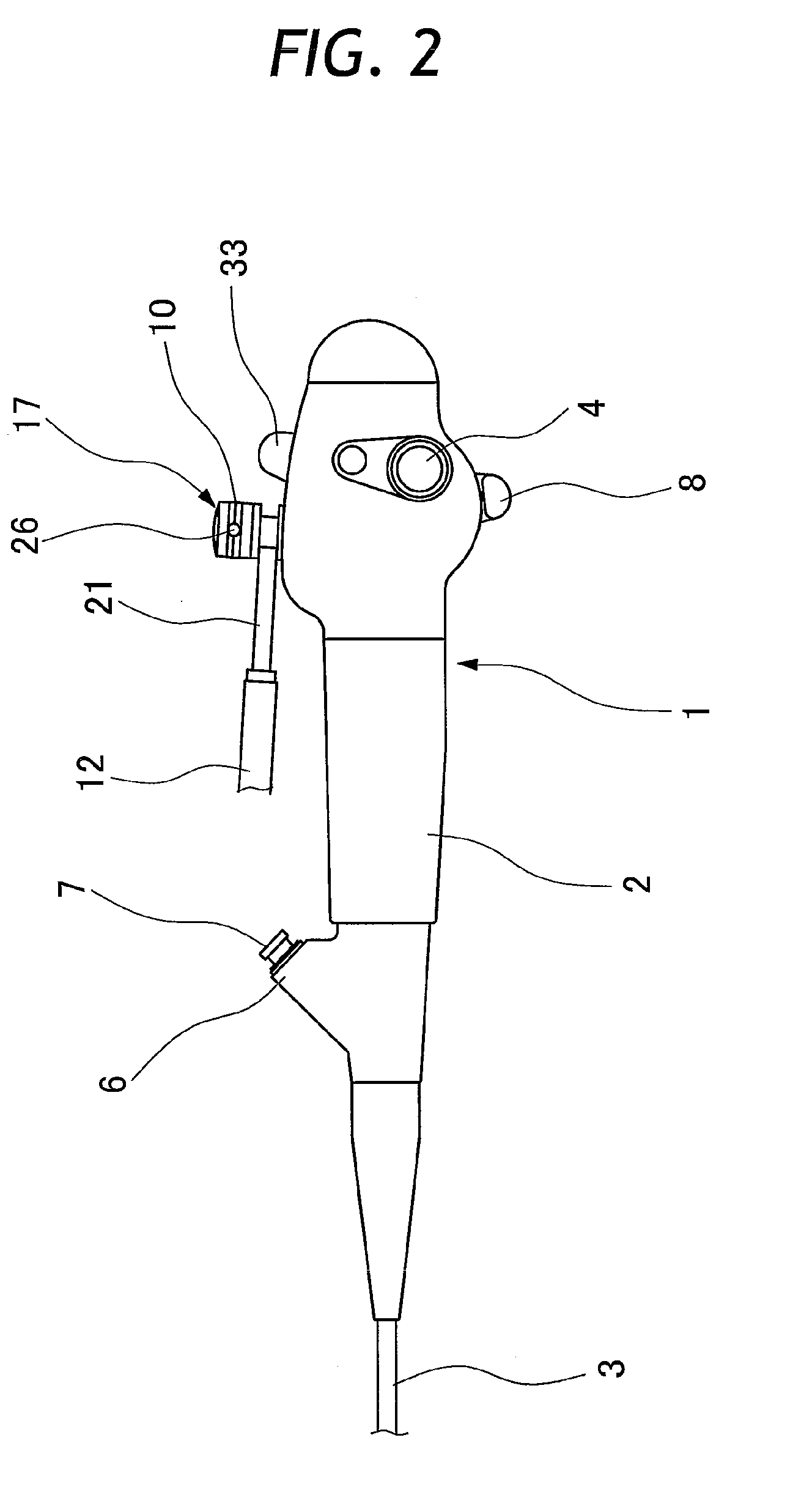
[0013]According to the present invention, in order to achieve the above-stated objectives, there is provided an endoscopic aspiration device for use on a manipulating head of an endoscope, to which a proximal end of an elongated insertion rod member is connected, the endoscopic aspiration device comprising a valve casing provided on the manipulating head in communication with an aspiration passage leading to a fore distal end of the insertion rod member, and a valve assembly unit composed of an assembly of a valve member and a valve guide member having a connector member extended out for connection to a proximal aspiration passage on the side of a suction source, the valve member being put in a sliding displacement along the valve guide member to bring the aspiration passage into and out of communication with the proximal aspiration passage, characterized in that the endoscopic aspiration device comprises: a coupling mechanism provided between the valve casing and the valve guide member of the valve assembly unit and adapted to couple the valve guide member with the valve casing in such a way as to permit the valve assembly unit to make turns about a center axis of the valve casing on the manipulating head; and the coupling mechanism including a coupling / uncoupling mechanism with a function of bringing the valve guide member of the valve assembly unit into and out of fitting engagement with the valve casing, and a lock-in mechanism with a function of retaining the valve guide member in a coupled state within the valve casing, preventing spontaneous dislodgement of the valve assembly unit from the valve casing.
[0014]A valve assembly unit which is largely composed of a valve guide member and a valve member is detachably fitted in a valve casing which is provided on the side of a manipulating head of an endoscope. In this regard, arrangements should be made to prevent spontaneous dislodgement of the valve assembly unit from the valve casing. In order to prevent the valve assembly unit from easily coming off the valve casing, it should be securely locked in the valve casing while the endoscope is in use including an aspirating operation. However, at the time of washing the endoscope after use, the valve assembly unit including the proximal aspiration passage on the side of a suction source should be easily uncoupled and dismantled from the valve casing.

Problems solved by technology

The aspiration valve employed in Patent Literature 1 is improved in washability but still has a problem.
However, it is very likely that the use of higher interlocking projection and stopper protuberance will make it difficult to extract the valve guide member from the valve casing for washing purposes each time after using an endoscope.

Method used


Image

  • Endoscopic aspiration device
  • Endoscopic aspiration device
  • Endoscopic aspiration device

Examples


second embodiment

[0065]Now, turning to FIGS. 10 through 14, there is shown the invention. In this embodiment, a valve casing and a valve assembly unit are disconnectibly coupled with each other through a coupling mechanism with locking and unlocking functions.

[0066]As shown in FIGS. 10 and 11, a valve casing 100 which is provided on a manipulating head 2 of an endoscope 1 is tapped with an external screw 100a on its outer peripheral surface, and an anchor nut 101 is threaded on the external screw 100a in such a way as to grip a housing 13 of the manipulating head 2 between the anchor nut 101 and a stopper flange 100b which is provided on the side of the valve casing 100. Threaded on the upper end of the valve casing 100 is a stationary flange member 102, which is formed with an upper large diameter portion 102a and a lower smaller diameter portion 102b on its outer peripheral side. The large and small diameter portions 102a and 102b are intervened by a transitory stepped wall surface 102c which is d...

first embodiment

[0067]Substantially in the same way as in the foregoing first embodiment, a valve assembly unit 103 is composed of a valve guide member 104 and a valve member 105. The valve guide member 104 is formed with a detachable flange portion 206. At a predetermined distance from the detachable flange portion 106, a rim fitting portion 107 is provided on an upper portion of the valve guide member 104 to receive a rim portion at the lower end of a skirt portion of a dome-like aspiration trigger member 25. A connector pipe 108 is connected to a reduced diameter portion of the valve guide member 104 between the detachable flange portion 106 and the rim fitting portion 107.

[0068]The valve assembly unit 103 is coupled with the valve casing 100 by inserting a lower portion of the valve guide member 104 into the valve casing 100. A seal member 109 is interposed between the inserted lower portion of the valve guide member 104 and the valve casing 100. On insertion, the valve guide member 104 is push...


PUM


Abstract

An endoscopic aspiration device is mounted on a manipulating head of an endoscope, from which an elongated insertion rod member is extended forward, the endoscopic aspiration device being composed of a valve casing which is mounted on the manipulation head in communication with an aspiration passage running through the insertion rod member, and a valve assembly unit including a valve member, a valve guide member and a connector member attached to the valve guide member to communicate same with a proximal aspiration passage on the side of a suction source. The valve member is put in a sliding displacement along the valve guide member to bring the aspiration passage into and out of communication with the proximal aspiration passage on the side of a suction source. The valve guide member is coupled with the valve casing through a coupling mechanism which permits to turn the valve assembly unit on and relative to the manipulating head. The coupling mechanism is arranged to perform a function of coupling and uncoupling the valve guide unit with and from the valve casing, and a function of locking the valve guide member in the valve casing to prevent spontaneous dislodgement from the latter.

Description

TECHNICAL FIELD[0001]This invention relates to an endoscopic aspiration device to be used on an endoscope for aspirating internal filth and body fluids from a body cavity.TECHNICAL BACKGROUND[0002]Generally, an endoscope is composed of a manipulating head and an elongated insertion instrument which is extended forward from the manipulating head for introduction into a body cavity in need of an endoscopic examination or treatment. In endoscopic examinations and treatments, an aspiration mechanism on an endoscope is resorted to for the purpose of observing an intracavitary site of interest in a clearly visible state. Namely, in case an intracavitary site under observation or treatment is covered with internal filth or body fluids like blood to such a degree as to make it difficult to observe the intracavitary site in question clearly, an aspiration mechanism is turned on to suck out covering internal filth and body fluids. In this regard, it has been the usual practice to utilize as a...

Claims


Application Information

Patent Timeline
Patent Type & Authority Applications(United States)
IPC IPC(8): A61B1/015
CPCA61B1/00068A61B1/00119A61B1/015A61M1/008A61B1/04A61B17/22A61M1/0047A61B1/018A61M1/7411A61M1/84
Inventor YAMANE, KENJI
Owner FUJIFILM CORP
Why Eureka
Try Eureka