Device for influencing an exhaust gas flow

Inactive Publication Date: 2009-09-03
EMCON TECHNOLOGIES GERMANY (AUGSBURG) GMBH
View PDF12 Cites 4 Cited by
  • Summary
  • Abstract
  • Description
  • Claims
  • Application Information

AI Technical Summary

Benefits of technology

[0010]The advantages of the coupling are therefore effective in particular if the rotation axis of the flap is substantially coaxial to the rotation axis of the drive motor.
[0011]Alternatively or additionally, the coupling can be configured as a thermal decoupling member that would and make

Problems solved by technology

The extremely hot exhaust gases (up to 750° C.) can heat the driving device excessively, which can result in a deterioration of the motor or in a thermally induced oversize of the motor.
Furthermore, excessive thermal expansion processes are generated in the force transmission member, which can lead

Method used


Image

  • Device for influencing an exhaust gas flow
  • Device for influencing an exhaust gas flow
  • Device for influencing an exhaust gas flow

Examples


Embodiment Construction

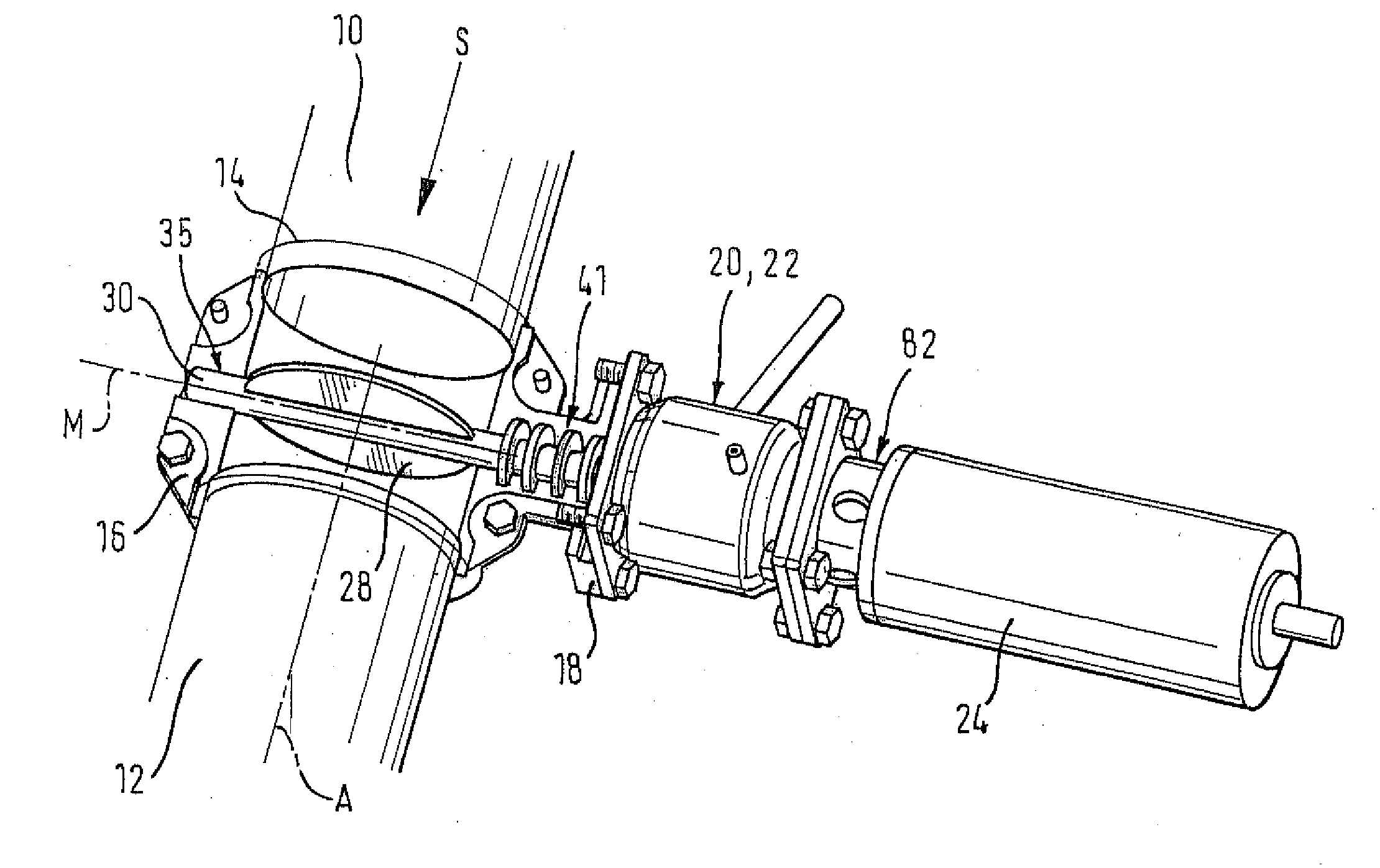
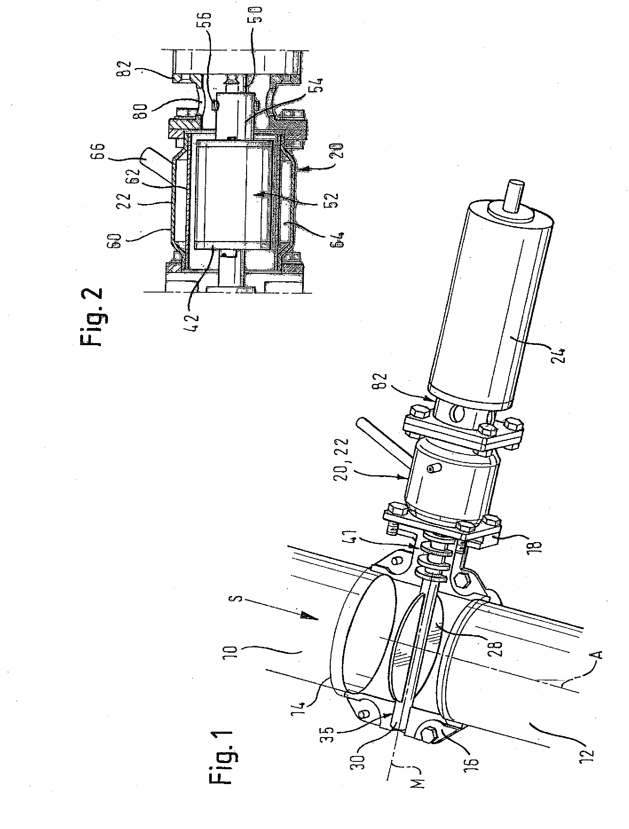
[0030]FIG. 1 shows a device for influencing an exhaust gas flow, more precisely a device for controlling the sound emission in an exhaust branch of a combustion engine. An exhaust gas supply pipe 10 supplies hot exhaust gas to the device, and a pipe 12 leads the exhaust gas away from the device towards an outlet. A line section on the side of the device is seated between the pipes 10, 12. This line section is concentric to the pipes 10, 12 and comprises two half-shells 14, 16 that are identical in terms of geometry, form and size.

[0031]FIG. 5 illustrates one of the half-shells 14, 16. A fastening flange 18 is integrally formed with the half-shells 14, 16 which are made of ceramic material or metal and are preferably cast. The fastening flange 18 includes two sections which are each associated with one of the half-shells 14, 16.

[0032]A unit comprised of a coupling 20 and of an active cooling system 22 surrounding the coupling 20 (see FIG. 2) is flanged to the fastening flange 18, and...


PUM


Abstract

A device for influencing an exhaust gas flow, in particular for controlling the sound emission in an exhaust branch of an engine, includes a closure member that is movably arranged in the exhaust gas flow. For example, the closure member comprises a flap driven by a motor to move the closure member in the exhaust gas flow. It is thus optionally possible to produce or influence pressure pulsations in the exhaust gas which lead to an audible sound emission. The device according to the invention provides for a so-called “sound design” of a combustion engine. The driving device (the drive motor and a force transmission member to the closure member) is equipped with an active cooling system.

Description

RELATED APPLICATIONS[0001]This application is the U.S. National Phase of PCT / EP2007 / 003294, filed 13 Apr. 2007, which claimed priority to European Application 06 009 061.0, filed May 2, 2006, and German Application 10 2006 034 177.5 filed 24 Jul. 2006.TECHNICAL FIELD[0002]The invention relates to a device for influencing an exhaust gas flow, in particular for controlling the sound emission in an exhaust branch of an engine. The device has a closure member movably arranged in the exhaust gas flow and a driving device for the closure member, which comprises a drive motor and a force transmission member to couple the drive motor to the closure member for drive. The closure member offers different flow resistances to the exhaust gas flow depending on its position in the exhaust gas flow.BACKGROUND OF THE INVENTION[0003]To meet the legal requirements relating to the sound emission of a vehicle, components such as mufflers for example, are mounted in the exhaust branch. The expenditure fo...

Claims


Application Information

Patent Timeline
IPC IPC(8): F01B31/16F16K31/02F01N7/00F01N13/08F01N13/14
CPCF01N1/165F01N2240/36F01N2260/022F02D9/04F01N2390/02F01N2560/08F01N2560/14F01N2260/024F01N1/168F01N1/18F01N9/00F01N13/14F01N13/16F01N2260/02F01N1/16
Inventor VENGHAUS, HELMUTGNAUERT, UWEKOHLRAUTZ, DANIELWENZEL, MICHAEL WOLFGANGSIEBALD, HUBERTUS
Owner EMCON TECHNOLOGIES GERMANY (AUGSBURG) GMBH
Why Eureka
Try Eureka