
Physical quantity measuring apparatus and electronic device

Active Publication Date: 2009-09-03
138 EAST LCD ADVANCEMENTS LTD
View PDF11 Cites 59 Cited by
  • Summary
  • Abstract
  • Description
  • Claims
  • Application Information

AI Technical Summary

Benefits of technology

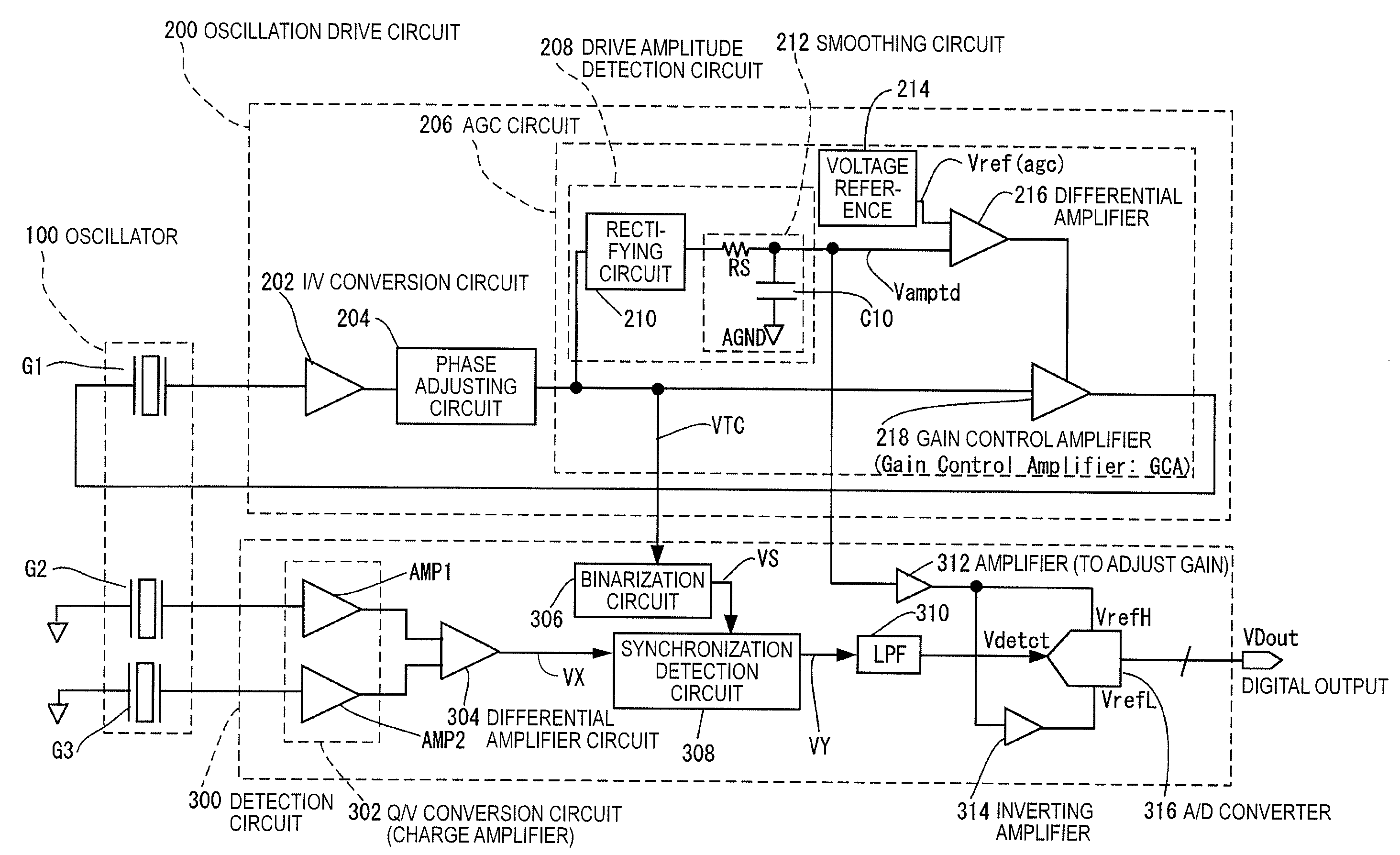
[0008]An advantage of some aspects of the invention is that it is possible to maintain the detection sensitivity to a physical quantity to be detected constant, for example, even when the amplitude of the drive oscillation varies, which enables detection at a high degree of accuracy.

Problems solved by technology

However, in a state where the amplitude has not been maintained constant by the AGC circuit, the detection sensitivity is non-constant.
Such being the case, the gyroscope in the related art has no choice but to render detection signals obtained in the oscillation start period invalid, which extends a start-up time until the desired detection sensitivity is achieved.
The problems discussed above, however, cannot be solved by the related art.
When an offset voltage (generated by various causes, such as a variance in characteristics of amplifiers and transistors) is superimposed on the reference bias AGND (analog ground, for example, AGND=VDD / 2) in a signal channel of the oscillation drive circuit (and the detection circuit), the offset voltage causes an error in achieving the ratiometricity with respect to the drive oscillation of the oscillator.
Further, the AF control mechanism provided, for example, to a single-lens reflex camera may possibly generate a mechanical impact when the AF motor is driven or stopped driving.

Method used


Image

  • Physical quantity measuring apparatus and electronic device
  • Physical quantity measuring apparatus and electronic device
  • Physical quantity measuring apparatus and electronic device

Examples


first embodiment

[0057]Firstly, the operation principle of the oscillatory gyroscope will be described. The oscillatory gyroscope is an angular velocity measuring apparatus using a piezoelectric oscillator made of crystal or ceramic or an electrostatic-driven oscillator made of silicon (physical quantity transducer). When an angular velocity is given to an oscillator in oscillation motion (drive oscillation), a Coriolis force acts in a direction orthogonal to the direction of oscillation and the oscillator consequently starts to oscillate in the direction of a Coriolis force (starts detection oscillation). The oscillation induced by a Coriolis force is at the same frequency as the drive oscillation and the amplitude thereof is proportional to the angular velocity that was inputted. It is therefore possible to measure the angular velocity applied on the oscillator by measuring the strength of the oscillation (detection oscillation) induced by a Coriolis force.

[0058]FIG. 11 is a view used to describe ...

second embodiment

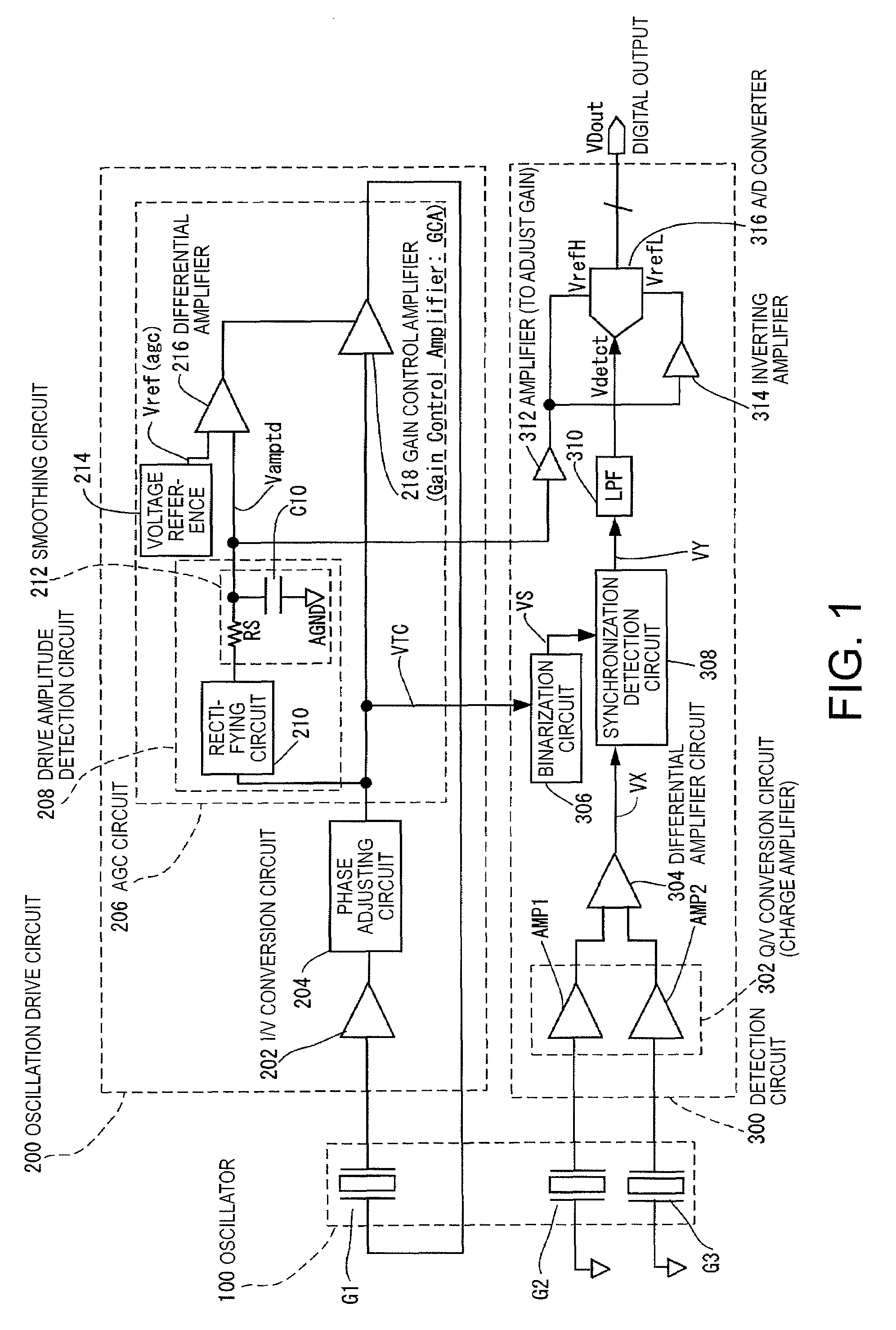
[0087]FIG. 9 is a view showing another example of the configuration of the oscillatory gyroscope of the invention. The basic configuration in FIG. 9 is the same as in FIG. 1 and a difference is the circuit configuration in a portion of the AGC circuit 206 responsible for a rectifying operation and an integrating operation. Another difference from FIG. 1 is that an offset adjusting circuit 320 is provided to the detection circuit 300.

[0088]In contrast to the first embodiment above in which the reference of the A / D converter 316 is controlled with a voltage corresponding to the drive amplitude, in this embodiment, the reference of the A / D converter 316 is controlled with a voltage corresponding to the drive amplitude and a voltage obtained by amplifying a deviation from the reference that determines the drive amplitude. In other words, the drive amplitude detection circuit and the differential amplifier are not used as the control circuit of a GCA, and instead, a rectifying and integr...

third embodiment

[0097]FIG. 10 is a view showing still another example of the configuration of the oscillatory gyroscope of the invention. The first embodiment above adopts the configuration in which the drive amplitude a is maintained constant by means of AGC. When the invention is used, however, an AGC circuit is no longer essential because the sensitivity to an angular velocity can be maintained constant independently of the drive amplitude a.

[0098]Accordingly, in this embodiment, a variance width of the drive amplitude in the oscillation drive circuit 200 is limited by an amplitude limiting circuit 500. In addition, the reference of the A / D converter 316 is controlled variably (adaptively) on the basis of the detection signal of the drive amplitude detection circuit 208. The amplitude limiting circuit 500 has a resistor R100 and diodes D10 and D20. A lower limit voltage V(L) is connected to the anode of the diode D10 and an upper limit voltage V(H) is connected to the cathode of the diode D20.

[0...


PUM


Abstract

A physical quantity measuring apparatus includes an oscillation drive circuit that forms an oscillation loop together with a physical quantity transducer and excites a drive oscillation of the physical quantity transducer, and a detection circuit that detects an analog detection signal outputted from the physical quantity transducer using a detection circuit first and thence converts the signal that has been detected into a digital signal using an A / D converter to output the digital signal. The oscillation drive circuit has a drive amplitude detection circuit that detects amplitude of the drive oscillation. A voltage level of a reference of the A / D converter included in the detection circuit is controlled on the basis of a detection output signal of the drive amplitude detection circuit.

Description

BACKGROUND[0001]1. Technical Field[0002]The present invention relates to a physical quantity measuring apparatus (for example, an oscillatory gyroscope that detects an angular velocity by detecting a Coriolis force with respect to the oscillation motion of an oscillator), and an electronic device.[0003]2. Related Art[0004]An example of the configuration of the oscillatory gyroscope is described, for example, in JP-A-2002-174520. According to this reference, an AGC circuit (Automatic Gain Control circuit) configured to maintain the amplitude of the drive oscillations constant is provided in an oscillation drive circuit that excites drive oscillations of the oscillator.[0005]The oscillatory gyroscope (hereinafter, referred to also as the gyroscope) of the cited reference is configured to maintain the drive amplitude constant by the AGC circuit as described above. However, in a state where the amplitude has not been maintained constant by the AGC circuit, the detection sensitivity is n...

Claims


Application Information

Patent Timeline
IPC IPC(8): G01C19/56G01C19/5607
CPCG01C19/5607
Inventor NOZAWA, TOSHIYUKI
Owner 138 EAST LCD ADVANCEMENTS LTD
Learn More