Injection molding machine and method of controlling the same

a technology of injection molding machine and injection molding machine, which is applied in the direction of auxillary shaping apparatus, manufacturing tools, food shaping, etc., can solve the problems of affecting the quality of injection molding, and the difficulty in satisfactorily recycling materials for injection molding, so as to reduce the installation space, prevent overload, and reduce the effect of cos

Active Publication Date: 2009-09-03
NISSEI PLASTIC IND CO LTD
View PDF8 Cites 20 Cited by
  • Summary
  • Abstract
  • Description
  • Claims
  • Application Information

AI Technical Summary

Benefits of technology

[0010]With the injection molding machine 1 and the controlling method thereof according to the present invention, the following remarkable benefits are obtained.
[0011](1) Since the first control mode M1 and the second control mode M2 can be selected according to molding materials even if different types of molding materials (conditions) are used, it is possible to share a single injection molding machine 1 for molding operations for different types of molding materials. Thus, it is unnecessary to purchase two types of injection molding machines according to different types of molding materials, and this results in advantages in cost, installation space and the like, and the different types of molding materials are handled by change of the controlling methods. Hence, it is possible to prevent an injection molding machine itself from becoming specific and complicated, and this contributes to further reduction in cost.
[0012](2) Since, even if molding materials contain different types of materials like recycle materials, optimum control is performed according to the property and condition of the molding materials that inevitably contain different types of materials, the molding quality and the evenness of the molding materials can be enhanced, even if the molding materials are uneven, irrespective of the degree of the unevenness. In particular, when the second control mode M2 is selected, overload is prevented. This contributes to improved energy saving in the injection molding machine as a whole.
[0013](3) According to one preferred aspect, the servo gain Ks on the pump pressure in the second control system Cs is set lower than the servo gain Kf on the pump pressure in the first control system Cf. Thus, it is possible to make more apparent the advantage (property) of the second control system Cs in which the screw speed is open-loop controlled and the pump pressure is controlled by feedback.
[0014](4) According to another preferred aspect, the injection pressure detection means 6 includes at least one of the nozzle resin pressure sensor 6a for detecting the pressure of resin (Pid) inside the injection nozzle 11 in the injection device 1i, the cylinder internal pressure sensor 6b for detecting the hydraulic pressure (Pid) inside the injection cylinder 12 and the mold resin pressure sensor 6c for detecting the pressure of resin (Pid) inside the mold 13. Thus, it is possible to select more preferable detection positions corresponding to operation processes, molding conditions and the like. This makes it possible to accurately perform control suitable for operation processes, molding conditions and the like.
[0015](5) According to another preferred aspect, the minor loop control system Cm for the drive motor 3 is provided in which the number of rotations of the drive motor 3 is detected by the rotary encoder 14, and based on this detection result, the number of rotations is controlled by feedback. Thus, it is possible to stabilize the number of rotations of the drive motor 3 and furthermore the discharge flow rate and pump pressure of the hydraulic pump 4.

Problems solved by technology

Therefore, when injection molding is conventionally controlled by feedback, it occurs that the property of the molding material (unevenness of the molding material) affects the molding quality more significantly than the control by the molding machine does.
Hence, conventional injection molding machines encounter difficulties in molding recycle materials satisfactorily, and this problem becomes apparent as a larger amount of different types of materials are included.

Method used


Image

  • Injection molding machine and method of controlling the same
  • Injection molding machine and method of controlling the same
  • Injection molding machine and method of controlling the same

Examples


Embodiment Construction

[0028]A preferred embodiment of the present invention will now be described with reference to the accompanying drawings. The accompanying drawings do not limit the scope of the invention but facilitate the understanding of the invention. A detailed description of well-known portions will be omitted for the purpose of preventing the invention from being unclearly described.

[0029]The configuration of an injection molding machine 1 of this embodiment will first be specifically described with reference to FIGS. 2 to 5.

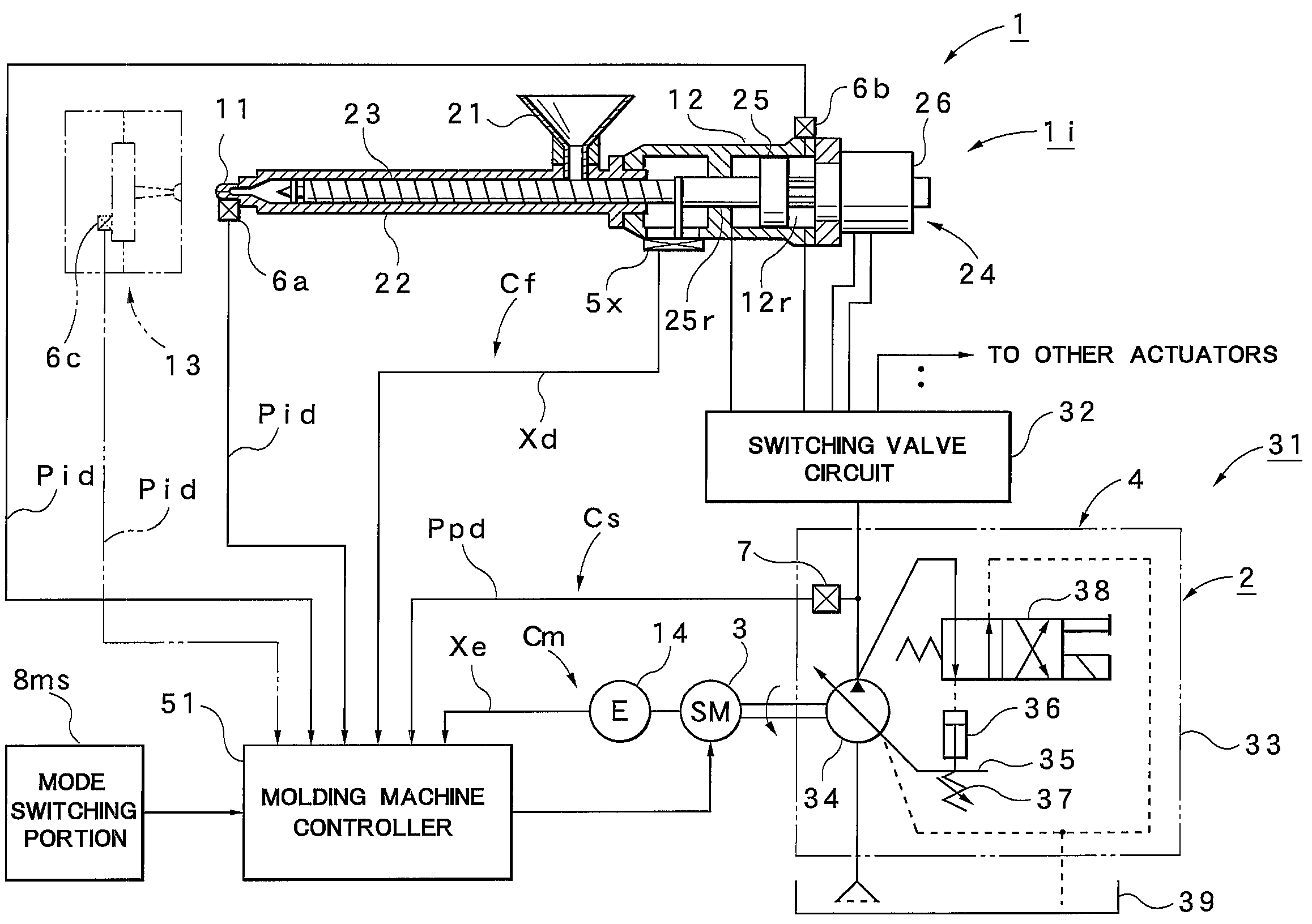
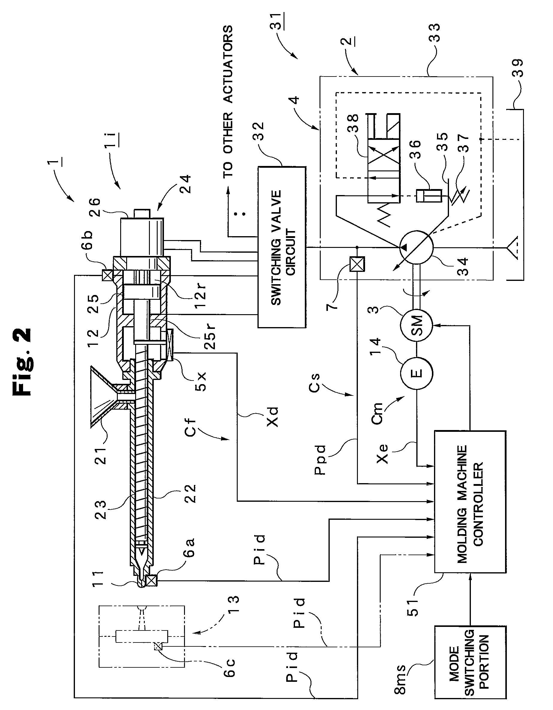
[0030]In FIG. 2, the reference numeral 1 represents the injection molding machine; the injection molding machine has an injection device 1i and a mold clamping device. The mold clamping device is not shown, and a mold 13 supported by this mold clamping device is only shown. The injection device 1i includes a heating cylinder 22 that has an injection nozzle 11 at its front end and a hopper 21 on its back. A screw 23 is inserted into the heating cylinder 22, and a screw driv...


PUM

PropertyMeasurementUnit
discharge flow rateaaaaaaaaaa
speedaaaaaaaaaa
pressureaaaaaaaaaa

Abstract

An injection molding machine 1 includes mode selection means 8 that can selectively switch between a first control mode M1 and a second control mode M2. In the first control mode M1, control is performed by a first control system Cf in which a screw speed is controlled by feedback with a speed detection value Vd that is detected by screw speed detection means 5 and a speed target value Vfc, and an injection pressure is controlled by feedback with a pressure detection value Pid that is detected by injection pressure detection means 6 and a pressure target value Pic, whereas, in the second control mode M2, control is performed by a second control system Cs in which the screw speed is open-loop controlled with a speed target value Vsc, and a pump pressure is controlled by feedback with a pressure detection value Ppd that is detected by pump pressure detection means 7 and that is related to the pump pressure of the hydraulic pump 4 and a pressure target value Ppc.

Description

TECHNICAL FIELD [0001]The present invention relates to an injection molding machine provided with a hydraulic drive source incorporating a hydraulic pump that variably controls the number of rotations of a drive motor to achieve the control of a discharge flow rate and a method of controlling such an injection molding machine.BACKGROUND ART [0002]Generally, injection molding machines incorporating an injection device and a mold clamping device are widely known as disclosed in JP-A-H04-79289 (patent document 1) and other documents. In this type of injection molding machine, typically, molding materials such as pellets are fed from the hopper of the injection molding machine into a heating cylinder, are plasticized and melted with a rotating screw in the heating cylinder and are measured, and then the molten resin measured through the forward movement of the screw is injected and filled into a cavity of the mold that is clamped by the mold clamping device. In this case, in order for t...

Claims


Application Information

Patent Timeline
Patent Type & Authority Applications(United States)
IPC IPC(8): B29C45/77
CPCB29C45/0001B29C45/77B29C2945/76006B29C2945/76113B29C2945/76187B29C2945/7621B29C2945/76933B29C2945/76257B29C2945/76307B29C2945/76381B29C2945/76498B29C2945/76598B29C2945/76665B29C2945/76214
Inventor HAKODA, TAKASHIKATO, TOSHIMIUNNO, YOSHIMOTOMURATA, HIROFUMINAKAMURA, KIYOSHI
Owner NISSEI PLASTIC IND CO LTD
Why Eureka
Try Eureka