
Arithmetic decoding apparatus

a decoding apparatus and arithmetic technology, applied in the field of arithmetic decoding systems, can solve the problems of difficult to predict the number of times the decoding process needs to be repeated, difficult to implement a circuit that can be driven at a high operating frequency to decode one or more symbols, and difficult to improve efficiency, so as to improve the performance of a context-adaptive binary arithmetic decoding process, reduce the scale of circuitry, and improve the performance of a

Inactive Publication Date: 2009-09-03
SONY CORP
View PDF6 Cites 14 Cited by
  • Summary
  • Abstract
  • Description
  • Claims
  • Application Information

AI Technical Summary

Benefits of technology

[0024]The present invention addresses the above-identified, and other problems associated with existing methods and apparatuses, and aims to improve performance of a context-adaptive binary arithmetic decoding process by simplifying the decoding process by decreasing the number of processing cycles per encoded bit, instead of by decreasing the number of processing cycles per decoded symbol.
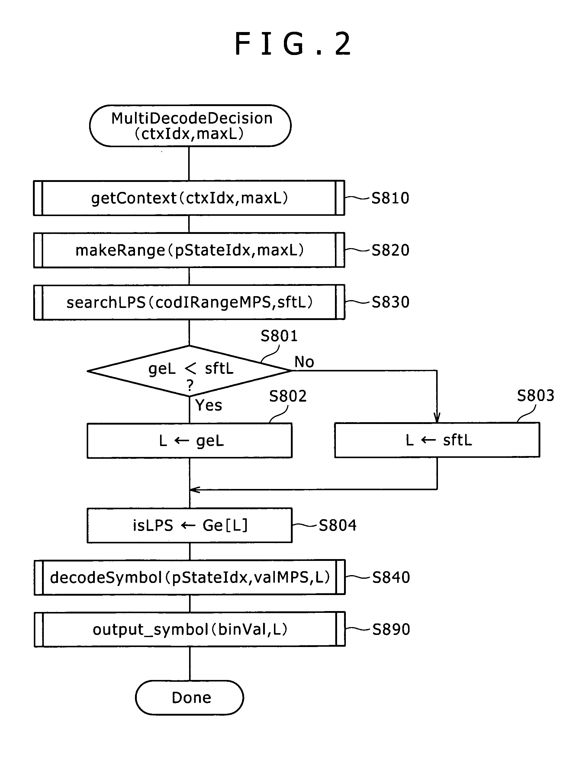
[0025]According to one embodiment of the present invention, there is provided an arithmetic decoding apparatus that decodes encoded data while updating a first state variable (e.g., codIRange) and a second state variable (e.g., codIOffset) based on a first context variable (e.g., pStateIdx[i]) and a second context variable (e.g., valMPS[i]), the first state variable being a basis for the decoding, the second state variable being an object to be decoded, the first context variable representing a probability state, the second context variable representing a most probable symbol, the arithmetic decoding apparatus including: a decoding information table that stores transitions of a range (e.g., codIRangeMPS[i]) of the most probable symbol and a range (e.g., codIRangeLPS[i]) of a least probable symbol within a range identified by the first context variable, and a number (e.g., sftL) of a symbol for which the range of the most probable symbol becomes less than a specific value, the decoding information table being referred to based on the first state variable and the first context variable; a number-of-symbols determination section configured to determining the number (e.g., a length L) of symbols in the encoded data that are to be decoded collectively, based on the transitions of the range of the most probable symbol and the range of the least probable symbol, the number of the symbol for which the range of the most probable symbol becomes less than the specific value, and the second state variable; and an output section configured to decode a symbol corresponding to the number of symbols that are to be decoded collectively, based on the second context variable, and outputting the decoded symbol. This makes it possible to identify a symbol or symbols that can be decoded collectively, based on information that is referred to based on the first state variable and the first context variable.
[0026]The present invention can improve the performance of a decoding process in a context-adaptive binary arithmetic decoding process, while at the same time reducing the scale of circuitry and so on.

Problems solved by technology

Moreover, it is generally difficult to predict the number of times the decoding process need be repeated.
In the case where a binary arithmetic code processing circuit is implemented by the circuit structures as illustrated in FIGS. 29 and 30, the processing is complicated since it involves many processes such as those by a shifter, a subtractor, a comparator, a table reference circuit, and a selector, and memory access, and this makes it difficult to implement a circuit that can be driven at a high operating frequency to decode one or more symbols per cycle.
It is therefore difficult to improve efficiency by increasing a circuit scale and implementing parallel processing.

Method used


Image

  • Arithmetic decoding apparatus
  • Arithmetic decoding apparatus
  • Arithmetic decoding apparatus

Examples


Embodiment Construction

[0062]Next, a preferred embodiment of the present invention will be described in detail below, with reference to the accompanying drawings.

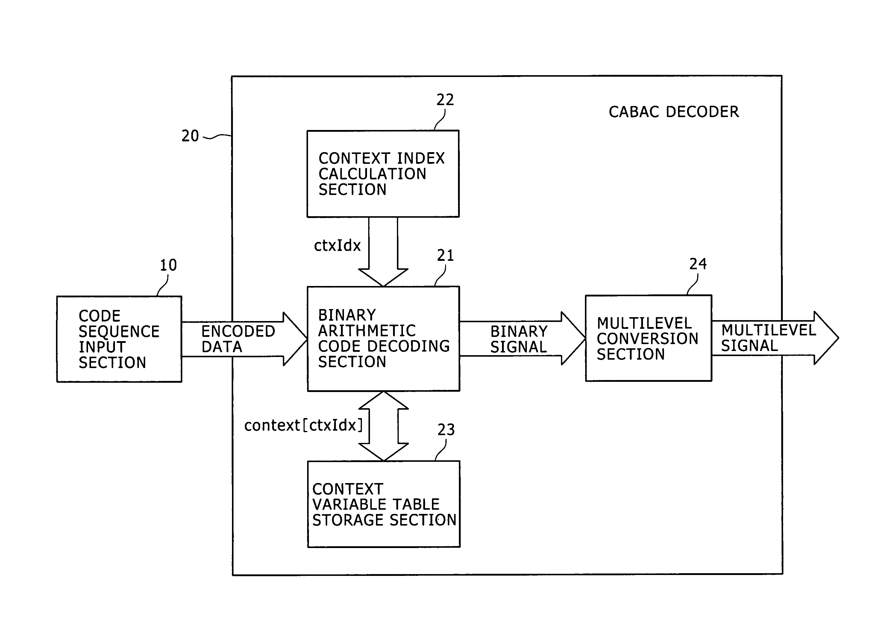
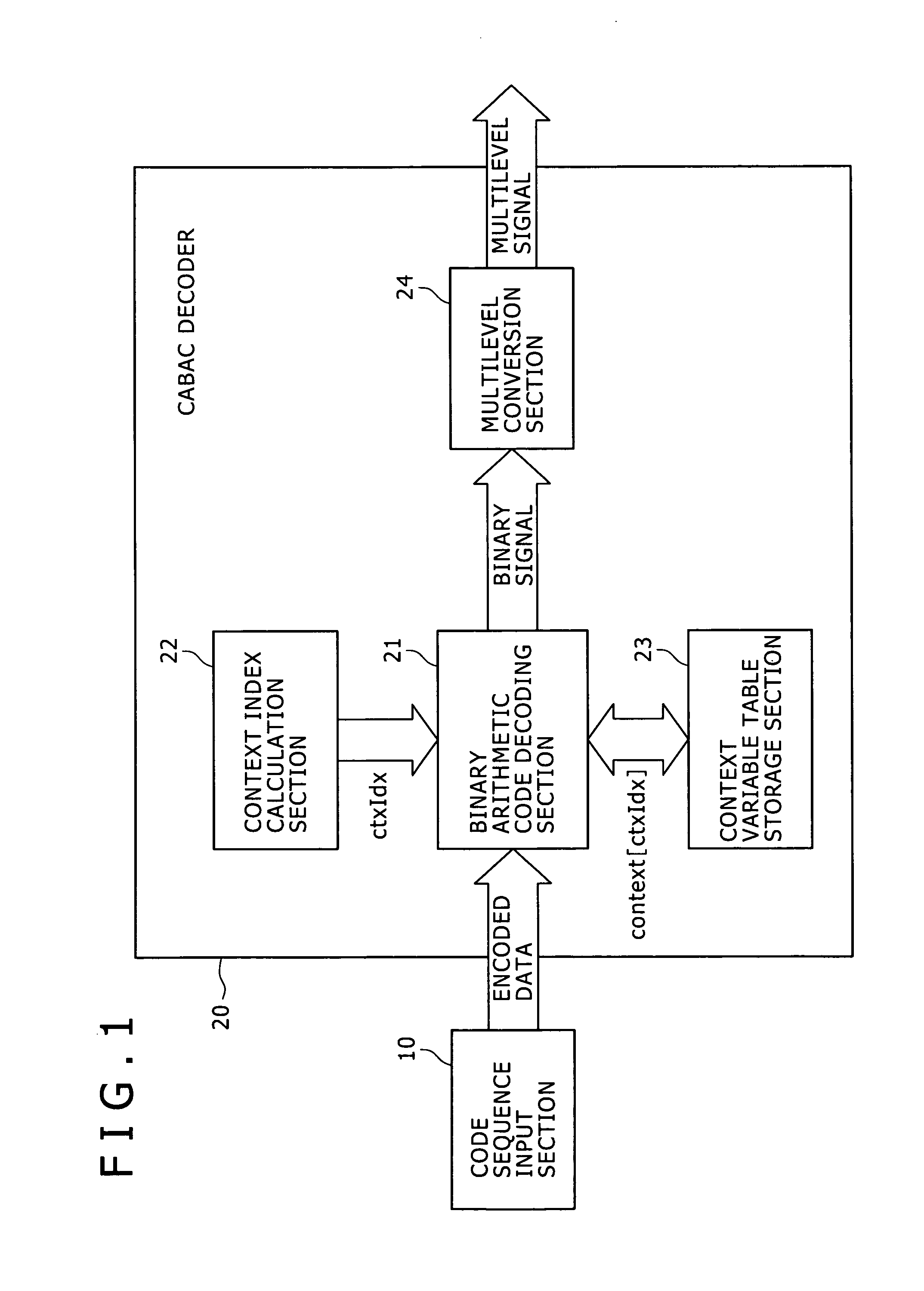
[0063]FIG. 1 illustrates an exemplary structure of a CABAC decoder 20 according to an embodiment of the present invention. The CABAC decoder 20 receives encoded data from a code sequence input section 10, decodes the encoded data to obtain a corresponding binary signal, and thereafter converts the binary signal into multilevel form to obtain a corresponding multilevel signal. The CABAC decoder 20 includes a binary arithmetic code decoding section 21, a context index calculation section 22, a context variable table storage section 23, and a multilevel conversion section 24.

[0064]The context index calculation section 22 calculates a context index (ctxIdx), and supplies the calculated context index ctxIdx to the binary arithmetic code decoding section 21.

[0065]The context variable table storage section 23 stores a context variable table, which conta...


PUM


Abstract

Disclosed herein is an arithmetic decoding apparatus that decodes encoded data while updating first and second state variables based on first and second context variables. The first context variable represents a probability state. The second context variable represents a most probable symbol. The arithmetic decoding apparatus includes: a decoding information table that stores transitions of a range of the most probable symbol and a range of a least probable symbol within a range identified by the first context variable, and a number of a symbol for which the range of the most probable symbol becomes less than a specific value; a number-of-symbols determination section configured to determine the number of symbols in the encoded data that are to be decoded collectively; and an output section configured to decode and output a symbol corresponding to the number of symbols that are to be decoded collectively.

Description

CROSS REFERENCES TO RELATED APPLICATIONS[0001]The present invention contains subject matter related to Japanese Patent Application JP 2008-049022, filed in the Japan Patent Office on Feb. 29, 2008, the entire contents of which being incorporated herein by reference.BACKGROUND OF THE INVENTION[0002]1. Field of the Invention[0003]The present invention relates to an arithmetic decoding system. In particular, the present invention relates to an arithmetic decoding apparatus for decoding data encoded with context-adaptive binary arithmetic coding (CABAC).[0004]2. Description of the Related Art[0005]The context-adaptive binary arithmetic coding (CABAC) is a form of entropy coding used in H.264, which has been standardized by ITU-T (International Telecommunication Union—Telecommunication standardization sector) (see ITU-T H.264). In the CABAC, various types of non-binary data are converted to binary so as to be represented as symbols of “0” or “1” before encoding. Then, they are encoded by...

Claims


Application Information

Patent Timeline
Patent Type & Authority Applications(United States)
IPC IPC(8): H03M7/00H03M7/40H04N19/00H04N19/423H04N19/426H04N19/44H04N19/91
CPCH03M7/4006
Inventor SAKAGUCHI, HIROAKI
Owner SONY CORP
Learn More