
Ground collision instrument for aircraft and marine vehicles

a collision instrument and aircraft technology, applied in the field of aircraft and marine vehicles, can solve the problems of aircraft, aircraft, aircraft, marine vehicles, and other obstacles on the ground, and achieve the effects of reducing the energy of an output pulse, reducing the sweep range of an antenna, and reducing the energy output puls

Active Publication Date: 2009-09-03
HONEYWELL INT INC
View PDF40 Cites 10 Cited by
  • Summary
  • Abstract
  • Description
  • Claims
  • Application Information

AI Technical Summary

Benefits of technology

[0010]Systems and methods of processing radar returns from a radar system are disclosed. An exemplary embodiment reduces energy of an output pulse emitted from a radar system; receives a plurality of radar returns from a plurality of objects that reflect the reduced energy output pulses emitted from the radar system; determines a surface area of interest based upon at least a current location of the installation vehicle; and filters the radar returns generated by objects that are located outside of the surface area of interest. Optionally, some systems and methods may reduce a sweep range of an antenna from which the reduced energy output pulses are emitted.

Problems solved by technology

Vehicles, in particular aircraft and marine vehicles, suffer the risk of collision with other vehicles, aircraft, trains, terminal structures, construction equipment and other obstacles on the ground and especially on runways where aircraft are concerned.
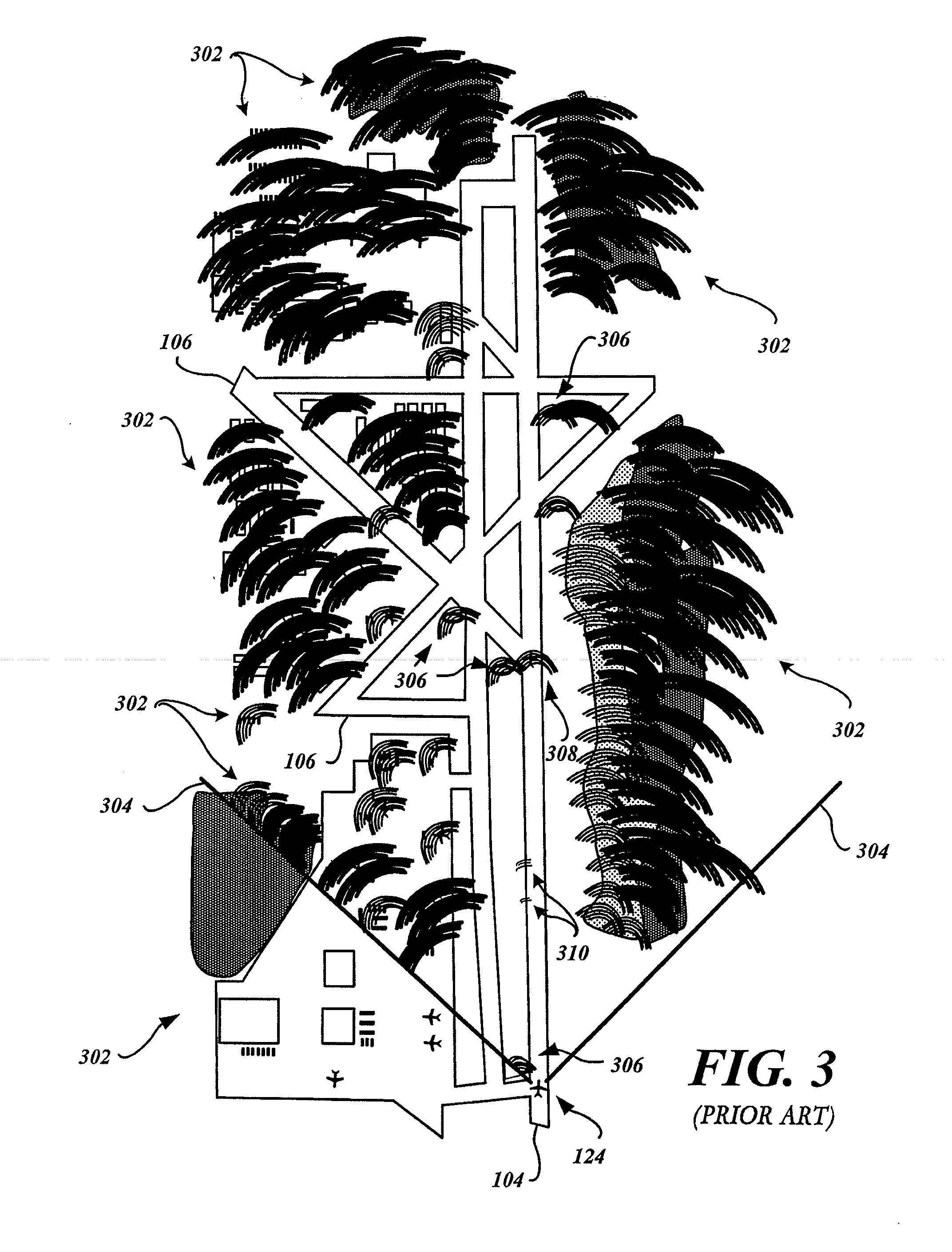
Further, there may be other structures, such as lights or the like (not shown) which also cause radar returns that also clutter the display.

Method used


Image

  • Ground collision instrument for aircraft and marine vehicles
  • Ground collision instrument for aircraft and marine vehicles
  • Ground collision instrument for aircraft and marine vehicles

Examples


Embodiment Construction

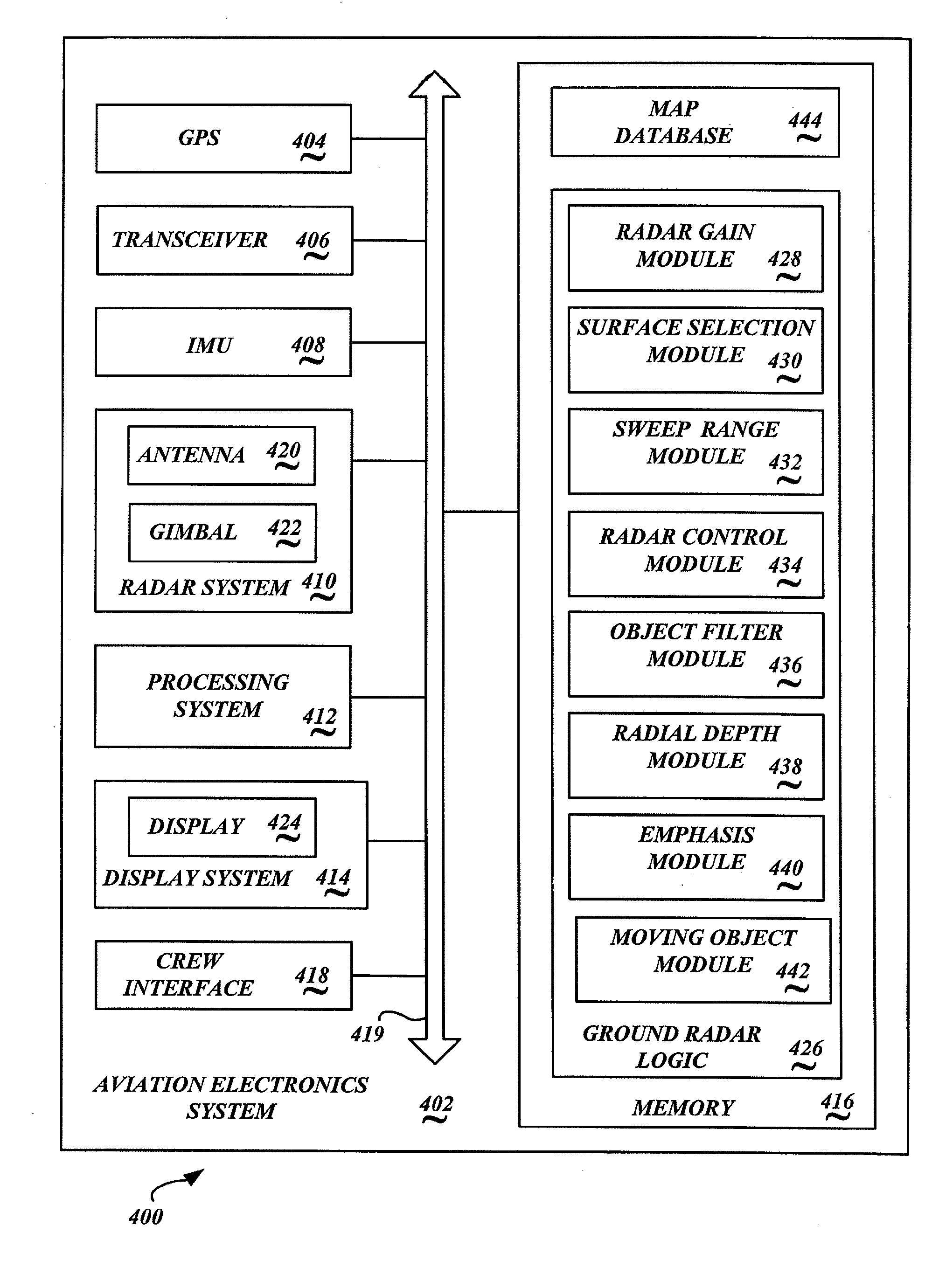
[0021]FIG. 4 is a block diagram of an exemplary embodiment of a ground radar system 400 implemented in an aviation electronics system 402 of an installation vehicle. Embodiments of the ground radar system 400 process radar information when an installation vehicle, such as an aircraft, is operating on the ground. Other embodiments are suitable for a marine radar, and process radar information when the installation vehicle, such as a ship, is operating in a port or around docks.

[0022]The aviation electronics system 402 includes a global positioning system (GPS) 404, a transceiver 406, an inertial measurement unit (IMU) 408, a radar system 410, a processing system 412, and a display system 414, a memory 416, and a crew interface 418. It is appreciated that the installation vehicle's aviation electronics system 402 includes many other components and / or systems that are not illustrated or described herein.

[0023]The above-described components, in an exemplary embodiment, are communicative...


PUM


Abstract

Radar return processing systems and methods are operable to process radar information when an installation vehicle is operating in proximity to a surface area of interest. An exemplary embodiment reduces energy of an output pulse emitted from a radar system; receives a plurality of radar returns from a plurality of objects that reflect the reduced energy output pulses emitted from the radar system; determines a surface area of interest based upon at least a current location of the installation vehicle; and filters the radar returns generated by objects that are located outside of the surface area of interest. Optionally, some systems and methods may reduce a sweep range of an antenna from which the reduced energy output pulses are emitted.

Description

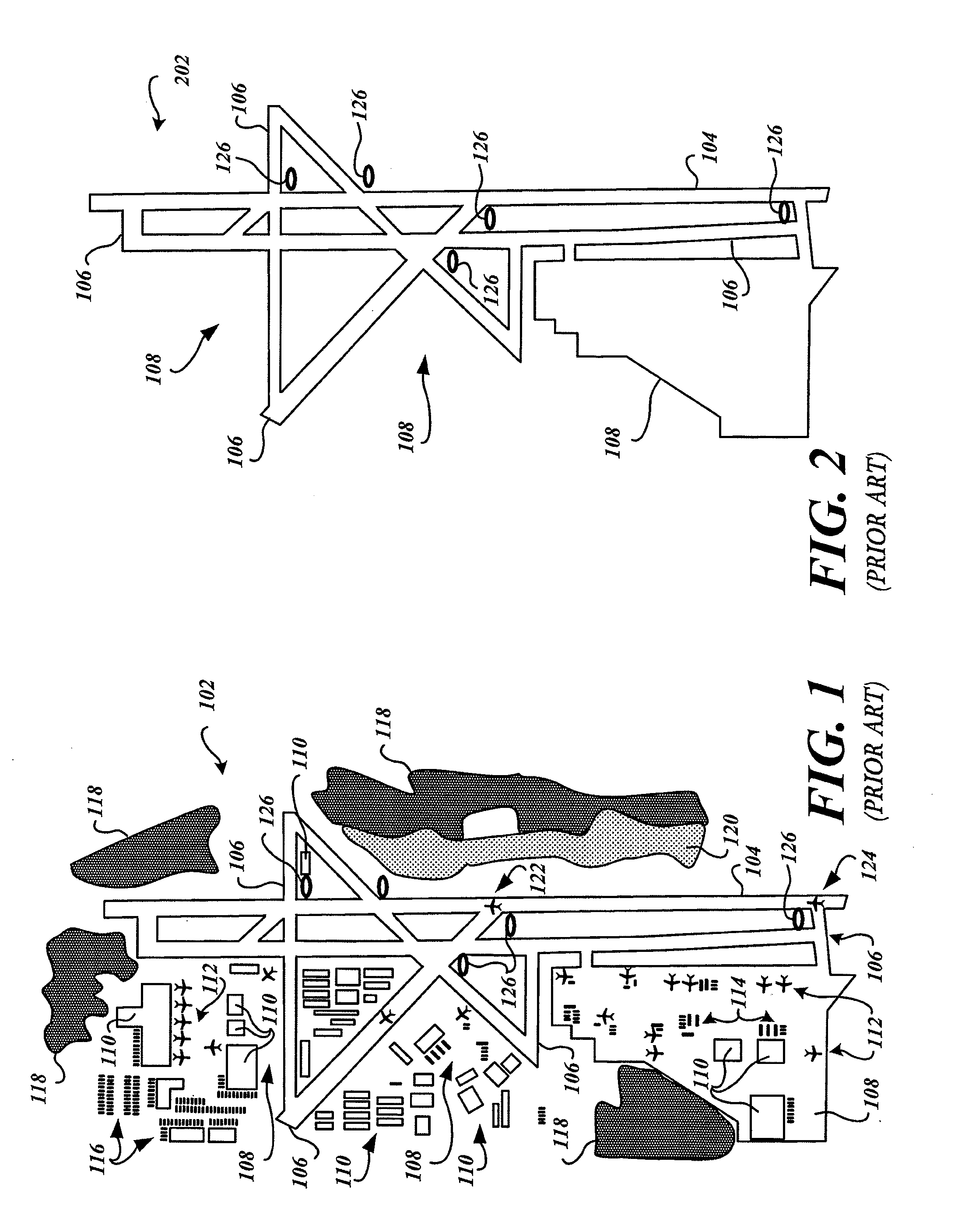
PRIORITY CLAIM[0001]This patent application claims priority from copending U.S. Provisional Patent Application Ser. No. 61 / 024,495 filed Jan. 29, 2008, and entitled, “Ground Collision Instrument for Aircraft and Marine Vehicles,” the contents of which are hereby incorporated by reference in its entirety.BACKGROUND OF THE INVENTION[0002]Vehicles, in particular aircraft and marine vehicles, suffer the risk of collision with other vehicles, aircraft, trains, terminal structures, construction equipment and other obstacles on the ground and especially on runways where aircraft are concerned. Weather radar is often turned off on the ground because of the relative high power of the transmitter operating in the X-band or higher and because of the ground clutter return.[0003]FIG. 1 is a plan view of a hypothetical airport 102. The hypothetical airport 102 includes a runway 104, several taxiways 106, a plurality of tarmac areas 108, and a plurality of terminal buildings 110. A plurality of pa...

Claims


Application Information

Patent Timeline
Patent Type & Authority Applications(United States)
IPC IPC(8): G01S13/93G01S13/937G01S13/931G01S13/934
CPCG01S7/06G01S2013/9335G01S13/9307G01S7/412G01S13/931G01S13/953G01S13/934G01S13/937Y02A90/10
Inventor BATEMAN, C. DONPOE, JOHN J.GLOVER, HOWARD
Owner HONEYWELL INT INC
Learn More