Object Ranging

Active Publication Date: 2009-09-03
MITSUBISHI ELECTRIC CORP
View PDF24 Cites 6 Cited by
  • Summary
  • Abstract
  • Description
  • Claims
  • Application Information

AI Technical Summary

Benefits of technology

[0017]According to a further independent aspect of the invention, in an object ranging system which operates by transmitting pulses derived from a frequency-swept signal and determining the beat frequency of a combination of the frequency-swept signal and its reflection from an object, a second (or higher) order harmonic is derived from the combination signal. Accordingly, determination of the beat frequency, and hence object range, is significantly enhanced.
[0018]According to a still further independent aspect of the invention, which may be used with or separately from the aspect described in the preceding paragraph, in an object ranging system which operates by transmitting pulses de

Problems solved by technology

Such a gating scheme minimises strong signals originating from antenna coupling, which can lead to unwanted effects in the receiver such as saturation of the receiver amplifier and/or the analogue-to-digital converter ADC.
However, because the period TD=1/FD of the beat signal decreases with measured distance D, for distances shorter than a certain critical value such condition cannot be satisfied.
Another limitation of short distance performance of FMICW radar results from the above-described gating scheme performed by the switch TRS.
The shape of such shortened pulses is more likely

Method used


Image

  • Object Ranging
  • Object Ranging
  • Object Ranging

Examples


example 1

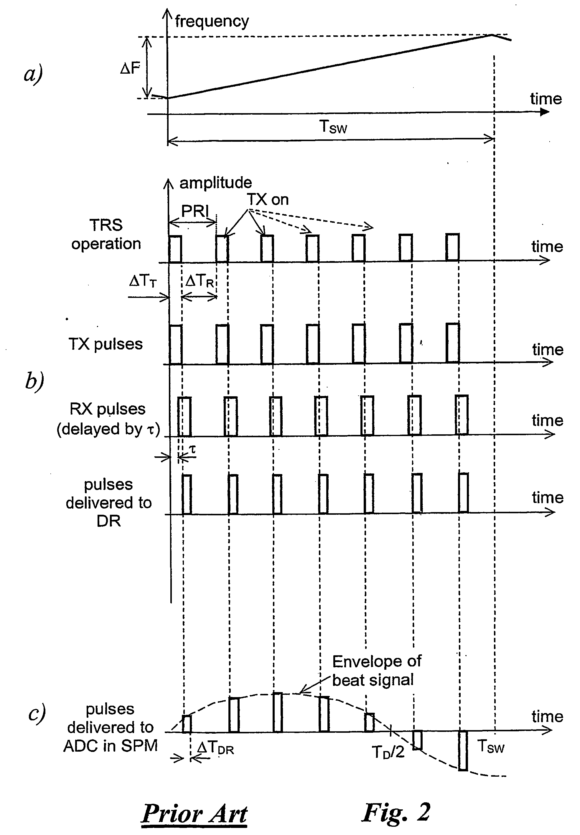
[0037]Assume that an automotive FMICW radar operating in the microwave range has the following parameters:[0038]duration TSW of a linear frequency sweep, TSW=4 ms;[0039]frequency excursion ΔF during the sweep, ΔF=80 MH;[0040]pulse repetition interval TPRI=2 μs.

[0041]FIG. 2a depicts schematically the relationship between time and frequency, the frequency / time characteristic, for the notional automotive radar under analysis.

[0042]Because, in this case, the pulse repetition interval TPRI is equal to 2 μs, the unambiguous range of distance measurement will extend to 300 m. In a radar employing a linear frequency sweep, the distance D to an obstacle is determined from the difference FD between two frequencies: the frequency of a transmitted waveform and that of a waveform reflected by the obstacle, where

FD=2DcSFT

where c is the speed of light; SFT is the slope of the frequency / time characteristic, given by

SFT=ΔFTSW=20[Hzns]

[0043]Therefore, in the considered case, an obstacle at a distance...

example 2

[0062]Consider again a notional automotive FMICW radar of Example 1, and assume that the duration of a linear sweep segment has been reduced from 2 μs to 400 ns. In such a case, the maximum operational distance decreases to 60 m, but the local slope of the frequency / time characteristic increases from the notional value of 20 Hz / ns to 100 Hz / ns. Consequently, for an obstacle at a distance of 3 m, the beat frequency FD will increase from 400 Hz to 2000 Hz. Therefore, the task of distance determination through spectral analysis within the time interval TSW=4 ms and frequency resolution of 1.3 / TSW=325 Hz (when a Hamming window is used) will now be much easier.

[0063]FIG. 8 is a simplified functional block diagram of a non-linear (but piecewise linear) frequency sweep generator NFSG for use in the arrangement of FIG. 11 to generate the waveform of FIGS. 7a and 7b.

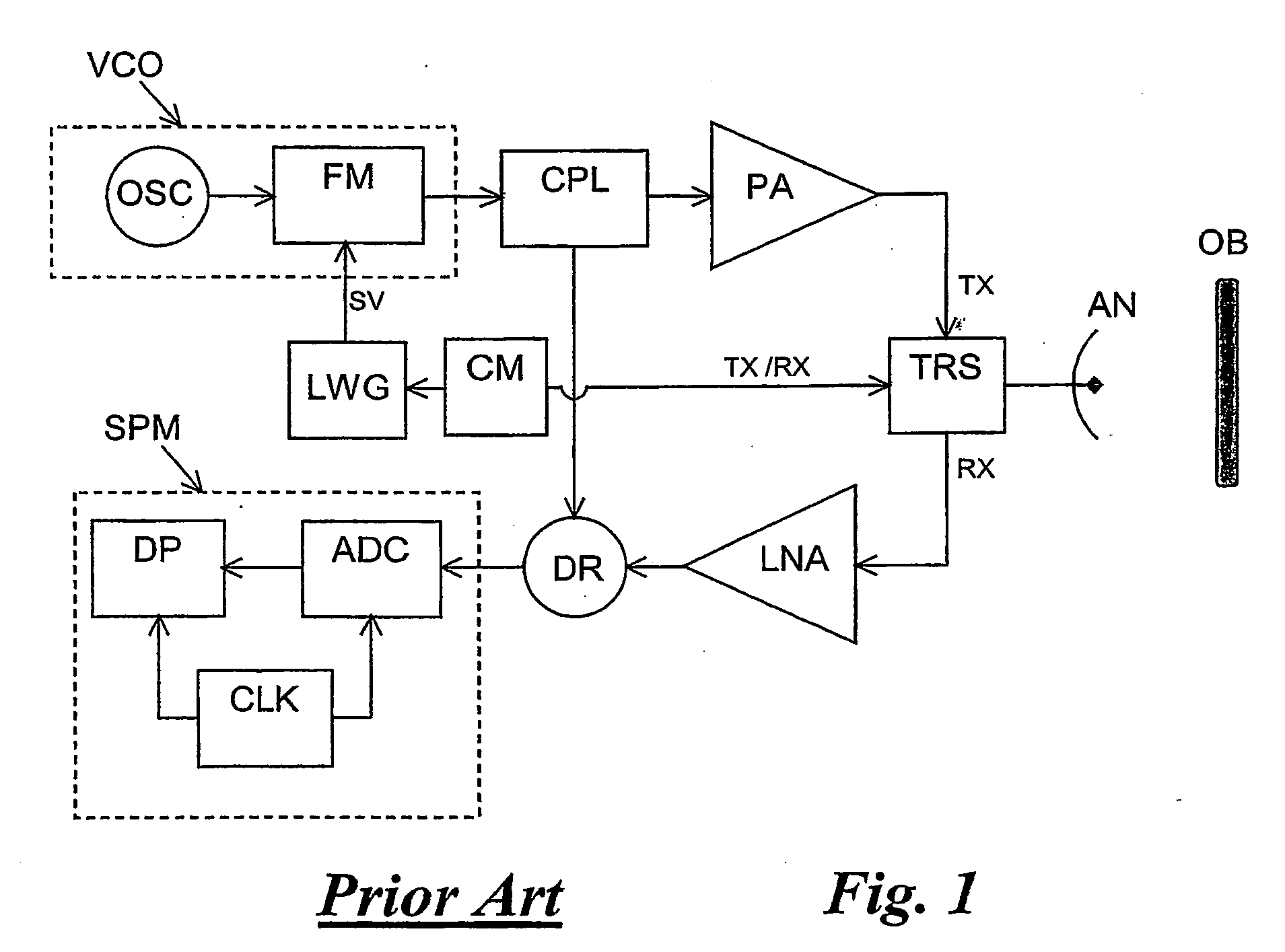
[0064]The non-linear frequency sweep generator NFSG comprises a voltage-controlled oscillator VCO, a frequency-sweep linearize...


PUM


Abstract

An object ranging system operates by transmitting pulses derived from a frequency-swept signal and determining the beat frequency of a combination of the frequency-swept signal and its reflection from an object. A second (or higher) order harmonic is derived from the combination signal. Accordingly, determination of the beat frequency, and hence object range, is significantly enhanced. The frequency sweep is such that frequency changes occur at a substantially higher rate at the beginning of each the pulse repetition interval than at the end. Accordingly, because the frequency changes are concentrated in the period of pulse transmission, even reflections ‘from a close object, where the time delay between the source signal and the reflection is very short, will cause a high beat frequency.

Description

BACKGROUND OF THE INVENTION[0001]1. Field of the Invention[0002]This invention relates to a method for determining the distance to an object, and is especially, but not exclusively, applicable to automotive radar systems which have microwave sensors to detect obstacles using a frequency modulated carrier combined with a pulsed transmission.[0003]2. Description of the Prior Art[0004]One of many systems, such as those described in WO 03 / 044559 A1, WO 03 / 044560 A1, U.S. Pat. No. 6,646,587 B2, JP 2000275333, JP2004333269 and JP2004144696, employed for automotive warning and collision avoidance is frequency modulated interrupted continuous wave (FMICW) radar. In such a system, shown in a block form in FIG. 1, the frequency of a carrier generated by an oscillator OSC is linearly swept in a periodic fashion with a period TSW over a predetermined frequency range ΔF using a frequency modulator FM in a voltage controlled oscillator VCO. A modulation pattern is provided by a linear waveform ge...

Claims


Application Information

Patent Timeline
IPC IPC(8): G01S13/34
CPCG01S13/34G01S13/282
Inventor SZAJNOWSKI, JERZY WIESLAWRATLIFF, PAULMACHOWSKI, WOJCIECH
Owner MITSUBISHI ELECTRIC CORP
Why Eureka
Try Eureka