Liquid ejecting head and liquid ejecting apparatus

Active Publication Date: 2009-09-03
SEIKO EPSON CORP
View PDF10 Cites 4 Cited by
  • Summary
  • Abstract
  • Description
  • Claims
  • Application Information

AI Technical Summary

Benefits of technology

[0011]In this configuration, since the first and second filters are arranged on two different planes, the distance between the liquid supply channels may be shortened, so that downsizing of the head is achieved. In addition, by forming the first member, the second member, and the third member integrally with the first and second filters by the first and second outer portions, areas for welding the first member, the second member, the third member, and the respective filters to each other individually are not necessary, so that the effective surface area of the filters may be increased, thereby further reducing the distance between the liquid supply channels.
[0012]Preferably, the first outer portion and the second outer portion are integrally formed. Accordingly, the manufacturing process may be simplified and, since the respective spaces are connected, a resin material can be filled into these spaces desirably. Therefore, the first and second outer portions may be formed desirably.
[0013]Preferably, the first filter is provided so as to project to the outside the area being clamped between the first member and the second member, a part of the area of the first filter projecting to the outside the area being clamped between the first member and the second member is clamped by the first outer portion, and the second filter is provided so as to project to the outside the area being clamped between the second member and the third member, a part of the area of the second filter projecting to the outside the area being clamped between the second member and the third member is clamped by the second outer portion. Accordingly, the first and second filters are reliably held by the first and second outer portions, and the first and second filters are prevented from generation of kink or separation.
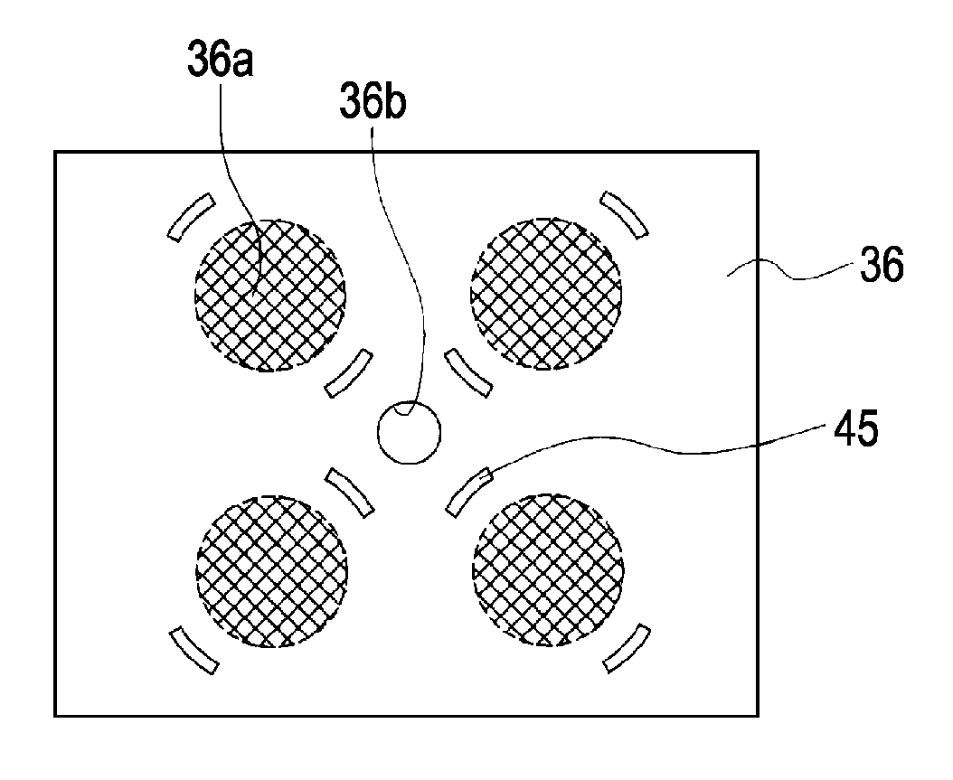
[0014]Preferably, the first filter and the second filter are formed with a plurality of penetrated portions, a portion of the first filter corresponding to the penetrated portion is clamped by the first outer portion, and a portion of the second filter corresponding to the penetrated portion is clamped by the second outer portion. Accordingly, when forming the first and second outer portions by integral molding, the first and second outer portions are reliably formed in a state in which the penetrated portions are penetrated therethrough. Therefore, the liquid supply channels may be reliably sealed, so that leakage of liquid or the like is prevented.
[0015]Preferably, the first outer portion and the second outer portion are present at different positions of the supply unit in plan view. Accordingly, the first and second outer portions may be provided in the proximity with the respective liquid supply channels, so that the liquid supply channels are sealed more reliably and leakage of liquid or the like is prevented.
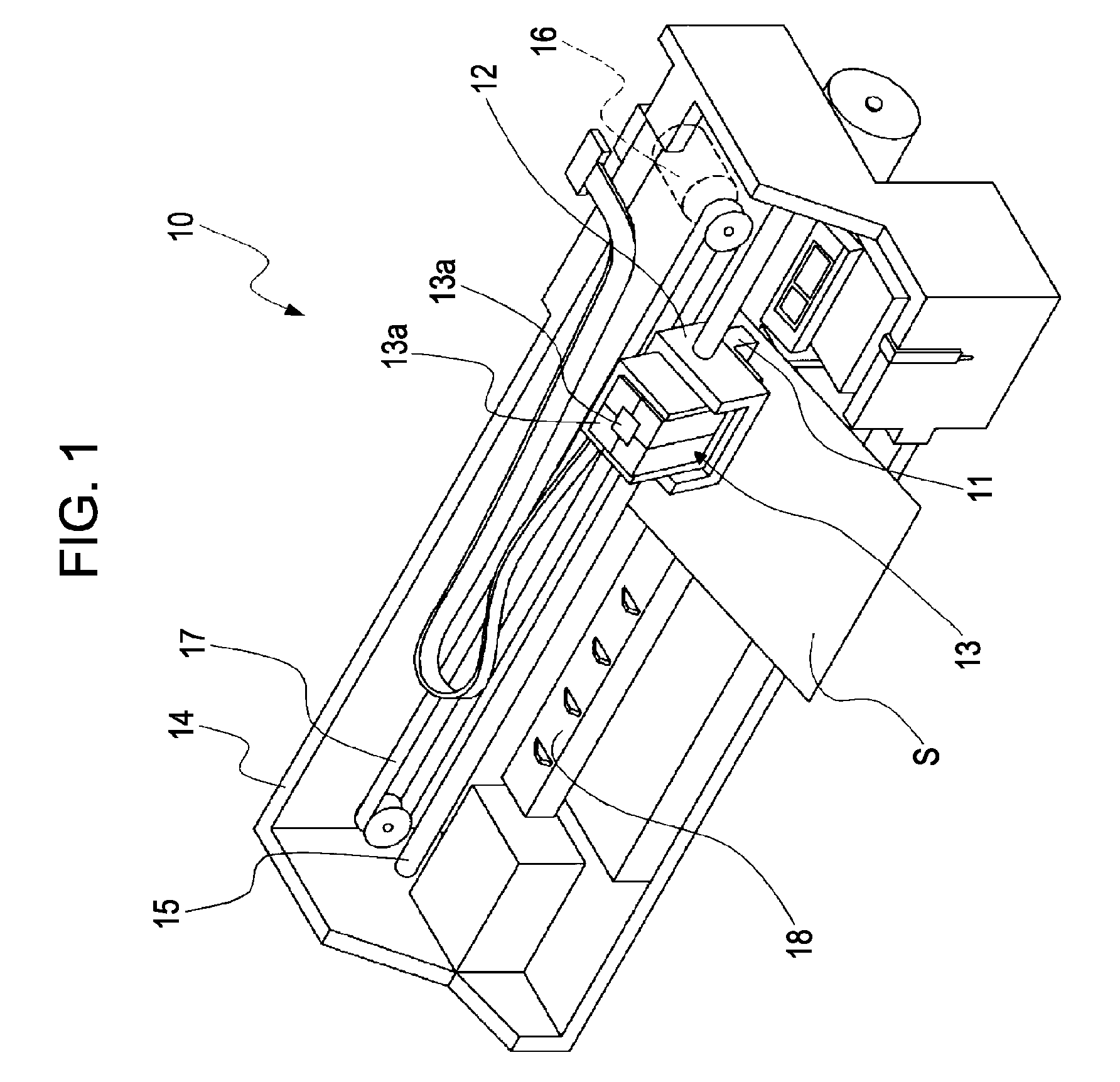
[0018]The invention also provides a liquid ejecting apparatus having the liquid ejecting head configured as described above. According to the embodiment of the invention, a compact liquid ejecting apparatus is achieved.

Problems solved by technology

The ink jet printhead as described above has a problem such that when air bubbles present in the ink in the ink cartridge or air bubbles mixed into the ink when mounting and demounting the ink cartridge are supplied to the head body, discharge failure such as missing dot might occur due to these air babbles.
However, in the configuration as described in JP-A-2000-211130, since a filter is provided in an area where the ink supply needle of the supply unit is fixed, the supply unit needs to have a size corresponding to the surface area of the filter, so that there arises a problem such that downsizing of the head is difficult.
For example, although downsizing the supply unit by reducing the distance between the ink supply needles is contemplated, since the area for welding the ink supply needles to the supply unit together with the filters is required, it is difficult to reduce the distance between the adjacent ink supply needles.
Although downsizing of the surface area of the filters by themselves is contemplated for example, since the dynamic pressure is increased, there arises a problem that the drive pressure for driving the pressure generating unit such as the piezoelectric element must be increased.
When the ink supply needles are fixed to the supply unit by heat adhesion, there is a risk of formation of a clearance between them, and hence there arises a problem such that ink might leak from this clearance.
In addition, when the filters and the ink supply needles are fixed individually to the supply unit, there arises a problem such that the manufacturing cost is increased to a high cost.
Such problems are present also in a liquid ejecting head configured to eject liquid other than ink in addition to the ink jet printhead.

Method used


Image

  • Liquid ejecting head and liquid ejecting apparatus
  • Liquid ejecting head and liquid ejecting apparatus
  • Liquid ejecting head and liquid ejecting apparatus

Examples


Embodiment Construction

[0029]The invention will be described in detail on the basis of embodiments.

[0030]FIG. 1 is a schematic perspective view of an ink jet printing apparatus according to a first embodiment of the invention. As shown in FIG. 1, an ink jet printing apparatus 10 as an example of a liquid ejecting apparatus in the invention is configured in such a manner that an ink jet printhead 11 as an example of a liquid ejecting head configured to discharge ink drops is fixed to a carriage 12, and the ink jet printhead 11 includes an ink cartridge 13 as liquid storing units in which ink in a plurality of different colors such as black (B), light black (LB), cyan (C), magenta (M), yellow (Y) and so on are stored detachably fixed thereto. The ink cartridge 13 includes a plurality of storage portions 13a for storing ink in respective colors and, for example, in this embodiment, four storage portions 13a are arranged around the storage portion 13a which is arranged at the center.

[0031]The carriage 12 havi...


PUM


Abstract

A liquid ejecting head includes a head body, a supply member having a first member, a second member, and a third member each having a liquid supply channel, the supply member including a first filter provided between the first member and the second member and a second filter provided between the second member and the third member; a first outer portion being provided between the first member and the second member, the first outer member being formed by integral molding for fixing the first member, the second member; a second outer portion being provided on the outer peripheries of the second member and the third member, the second outer portion being formed by integral molding for fixing the second member, the third member, and the second filter.

Description

BACKGROUND[0001]1. Technical Field[0002]The present invention relates to a liquid electing head configured to eject liquid and a liquid ejecting apparatus having the same and, specifically, an ink jet printhead configured to eject ink as the liquid and an ink jet printing apparatus.[0003]2. Description of the Related Art[0004]In an ink jet printhead as an representative example of a liquid ejecting head, generally, ink is supplied from an ink cartridge as a liquid storage unit in which ink is filled to a head body via ink supply needles as ink supply member detachably inserted into the ink cartridge and ink flow channels formed in a supply unit such as a cartridge case in which the ink cartridge is held, and the ink supplied to the head body is discharged from nozzles by driving a pressure generating unit such as a piezoelectric element provided in the head body.[0005]The ink jet printhead as described above has a problem such that when air bubbles present in the ink in the ink cart...

Claims


Application Information

Patent Timeline
IPC IPC(8): B41J2/175
CPCB41J2/17563
Inventor OWAKI, HIROSHIGEKANAYA, MUNEHIDE
Owner SEIKO EPSON CORP
Why Eureka
Try Eureka