Image Guidance System for Deep Brain Stimulation

a brain stimulation and image guidance technology, applied in the field of neurosurgery treatment of neurological diseases and disorders, can solve the problems of inability to define the precise target tissue, lack of information that would allow the surgeon to identify the required tissue function, and limited spatial volume of track data, so as to improve the precision of microelectrode targeting

Inactive Publication Date: 2009-09-03
UNIV OF FLORIDA RES FOUNDATION INC
View PDF5 Cites 50 Cited by
  • Summary
  • Abstract
  • Description
  • Claims
  • Application Information

AI Technical Summary

Benefits of technology

[0005]The invention relates generally to an image guidance system for intra-operative use during DBS surgery. More particularly, in the development of various aspects of the inventive system, computer...

Problems solved by technology

Although the DBS procedure is advanced, the standard methodology used, prior to the development of the inventive system, encompasses many manual steps that hinder the surgical operation and the ability of the medical team to accurately target the point of interest.
While the MR data allows the surgeon to identify anatomic structures, it unfortunately does not contain information that would allow the surgeon to identify the required tissue function.
Thus, this structural description alone can get one close to the target, but it does not allow for the definition of the precise target tissues.
Unfortunately, these track data are very limited in the spatial volume that they comprise.
While it would be optimal to complete many tracks, it is typically in the best interest of the patient that the number of tracks is limited.
Thus, the map created from the patient microelectrode data is typically sparse in its information and is not sufficient to provide all of the required information to refine the targeting.
The atlas itself only has a finite number of slices through the cadaver brain (as it was created by physical slicing of this brain), and is not able to be interpolated due to its non-digital nature.
Unfortunately, targeting a particular position in the patient's anatomy that corresponds to an analogous plane in an atlas is not feasible for readily apparent practical reasons.
In addition, due to clinical requirements of choosing a safe path for the tracks, the...

Method used


Image

  • Image Guidance System for Deep Brain Stimulation
  • Image Guidance System for Deep Brain Stimulation
  • Image Guidance System for Deep Brain Stimulation

Examples


example 1

Digitized Atlas of Neuroanatomic Structures

[0104]A central component of various systems and embodiments in accordance with the invention is a digitized three-dimensional brain map. This Example describes the development of a digitized version of a printed atlas of neuroanatomy suitable for use in an image guidance system for DBS surgery.

[0105]1.1 Introduction.

[0106]The Schaltenbrand-Bailey atlas has been used exclusively by neurosurgeons so this is the atlas that was chosen to be digitized. The Schaltenbrand-Bailey atlas is based on a study of 11 brains and is a collection of photographed images and contours of macroscopic and microscopic sections. Because only the myelin stained microseries, depicting subcortical structures, was of concern for the creation of the digitized atlas, only two of those 111 brains were of interest for this work.

[0107]The myelin stained microseries is composed of sections from three different cuts, i.e., coronal, sagittal, and axial. The coronal series is...

example 2

Development of a Clinical System for Deep Brain Stimulation

[0133]This Example further describes several novel computer programs suitable for use in positioning stimulation electrodes in an image guided DBS system in accordance with the invention, and the development of a clinical system for DBS, based on these programs.

[0134]2.1 Overview

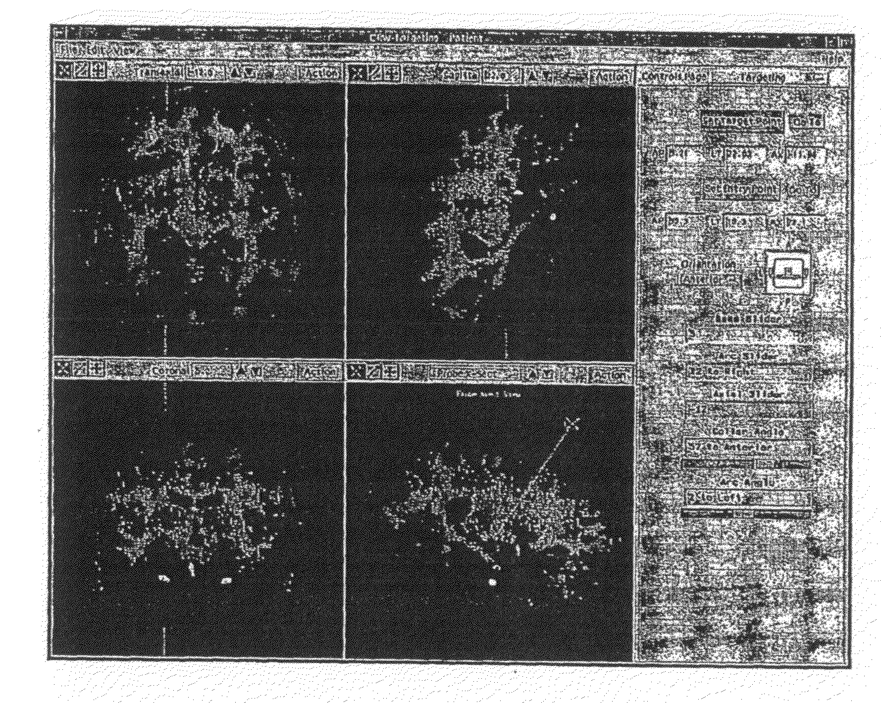
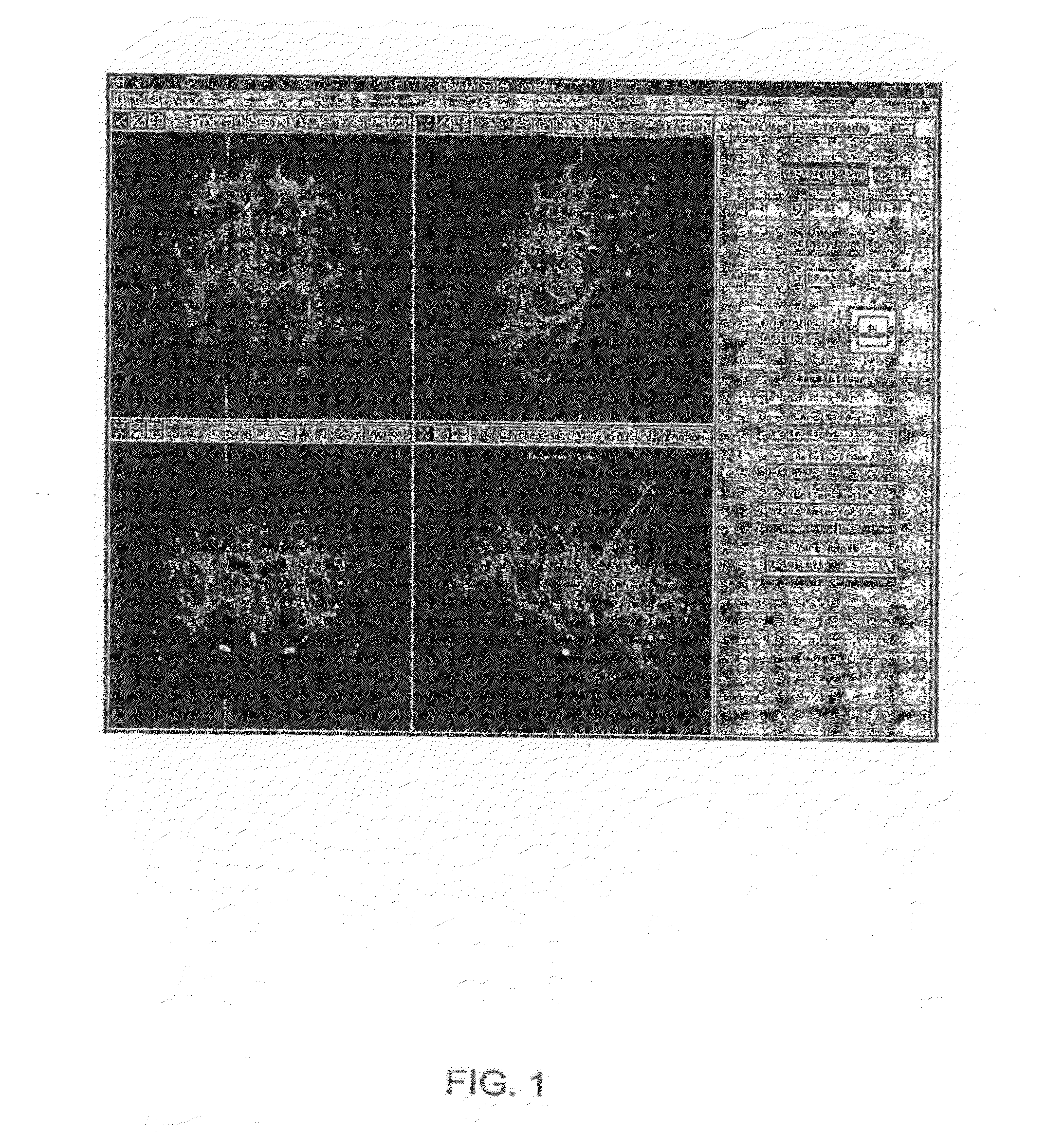
[0135]A set of computer programs with graphic user interfaces was created in Matlab to implement clinically useful viewing of the atlas and microelectrode data. More specifically, a program, named MRAtlas was created to view MR images with contours of the atlas superimposed on them. Another program named DBS Data Acquisition program was created to intraoperatively obtain microelectrode data for display and plotting purposes. A final program, MicroAtlas, was created to view the acquired microelectrode data on the superimposed atlas contours. These programs together provide a framework for clinical implementation of the improved DBS guidance system, an...

example 3

Evaluation of Clinical System for DBS

[0174]This Example describes methods used to verify the algorithms and systems developed in accordance with the invention.

[0175]3.1 Overview

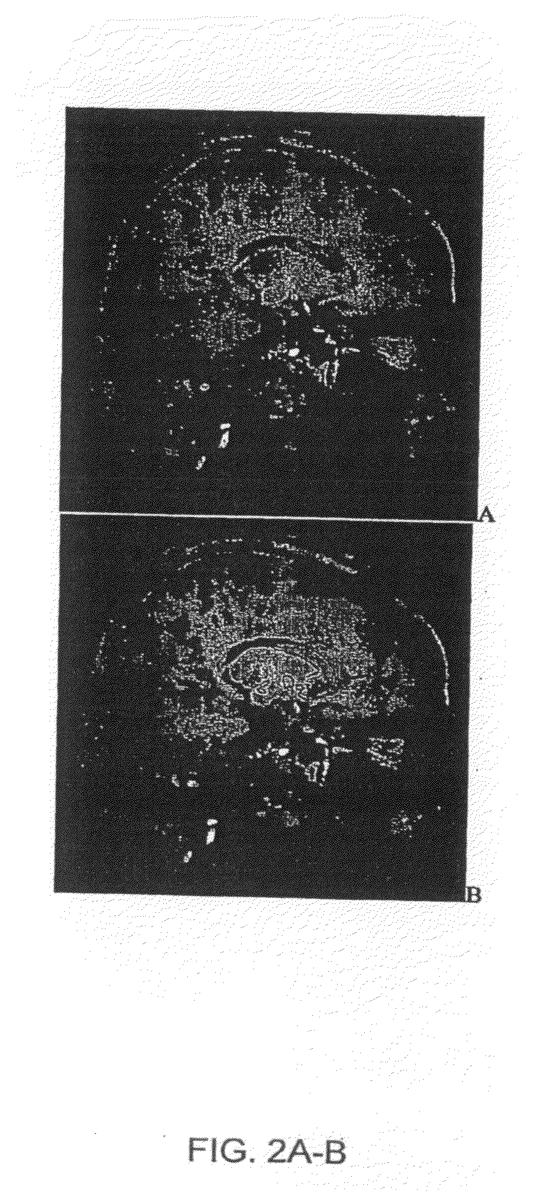
[0176]The Examples above describe the creation of the systems and development of algorithms used to improve the targeting in DBS. Verification of the algorithms and systems was completed using both qualitative and quantitative methods. The two algorithms that required validation are the atlas creation and microelectrode data matching algorithms. Qualitative verification of the atlas consisted of viewing of the atlas slice-by-slice along the planes of the print atlas, using the Atlas Evaluator program, and using the Atlas Slicer program. The automated microelectrode data matching algorithm results can be viewed using the MicroAtlas program and was subjectively evaluated by comparing to manual matching or form fitting. The results shown in this Example are for analysis of the systems described above.

[0177]3.2 E...


PUM


Abstract

This invention provides computerized image guidance systems for deep brain stimulation (DBS) surgery and related methods that improve accuracy of positioning of electrodes in the brains of subjects. Image guidance systems in accordance with the present invention incorporate advanced features such as capability of displaying, in any desired plane of view, a digitized three-dimensional neuroanatomical brain map that can be form fitted to a patient's medical images, such as brain MR images, and capability of displaying on the patient's medical images both the contours of anatomic structures from a digitized brain map, and digitized electrode recording data obtained intra-operatively.

Description

CROSS-REFERENCE TO RELATED APPLICATIONS[0001]The present application claims the benefit of priority under 35 U.S.C. § 119(e) to U.S. Provisional Patent Application No. 60 / 765,317, entitled Image Guidance System for Deep Brain Stimulation, filed Feb. 3, 2006, the disclosure of which is incorporated herein by reference in its entirety.FIELD OF THE INVENTION[0002]The invention generally relates to methods for treating neurological diseases and disorders by neurosurgery. More particularly, it relates to therapeutic methods and systems for electrically stimulating the brain by deep brain stimulation (DBS).BACKGROUND[0003]Deep brain stimulation (DBS) therapy has grown as an appealing alternative or supplement to medication for treatment of neurological disorders including movement disorders. The surgical requirements for effective DBS demand accurate, sub-millimeter targeting of the region to be stimulated. Multiple techniques are utilized to provide the neurologist and neurosurgeon with ...

Claims


Application Information

Patent Timeline
IPC IPC(8): G06K9/00G06T15/00G06K9/36G06T15/08
CPCA61B5/055A61B6/03A61B6/501A61B6/5247G06T2210/41A61B19/52A61B19/56A61B2019/5289G06T15/08A61B19/201A61B5/4082A61B90/36A61B34/25A61B2090/364A61B90/11
Inventor BOVA, FRANK J.SUDHYADHOM, ATCHAROKUN, MICHAEL S.FOOTE, KELLY D.
Owner UNIV OF FLORIDA RES FOUNDATION INC
Why Eureka
Try Eureka