Multi-Purpose Surgical Instrument With Removable Component

a surgical instrument and removable technology, applied in the field of surgical instruments, can solve the problems of severe constraints on the space available for the placement of surgical instruments, the inability to adjust the angle of the incision, and the inability to adjust the incision depth, etc., and achieve the effect of convenient and fast adjustment, convenient operation and convenient operation

Active Publication Date: 2009-09-03
LIEPONIS JONAS V
View PDF18 Cites 69 Cited by
  • Summary
  • Abstract
  • Description
  • Claims
  • Application Information

AI Technical Summary

Benefits of technology

[0021]The combined visualization and suction device provides a number of significant advantages over previous systems. For example, in minimally invasive surgery, the incision size is greatly reduced but the depth of the incision remains constant with open surgical procedures. This means the angle at which the surgical instruments enter and are placed in the procedure area is relatively large (i.e., approaching perpendicular). Therefore, the fewer instruments simultaneously inserted into the incision and the smaller in diameter each instrument, the greater flexibility the surgeon has to manipulate the surgical instruments.
[0022]The combination of suction and visualization instruments into one surgical device provides the distinct advantage of alleviating space constraints for the surgeon, especially is this so when the outside diameter (OD) of the combination instrument is essentially the same size as a suction only tool or perhaps only marginally larger.
[0023]In another advantageous embodiment, the suction tip of the combination device is provided made of a transparent or translucent material such that visual obstruction to the work area is minimized. The configuration of the fiber optic strands may be selected such that they may be used to effectively illuminate the work area while not providing an obstruction to visualization.
[0026]To achieve uniformity of angle in the various optical fibers, the optical fibers may be cut or machined by adhering the optical fibers to a sheet of material and then cutting or machining the ends at a uniform angle. The optical fibers may then be applied or adhered to a suction cannula providing all of the fibers at a uniform orientation facing toward the visualization field to maximize illumination.
[0027]It is further conceived that the combination surgical device be kept as inexpensive to manufacture as reasonably possible such that incidental contact and damage caused to the combination surgical device will not greatly impact operating costs. To accomplish this, the combination surgical tool may be provided as a disposable device providing for reduced costs.

Problems solved by technology

Therefore, the incision size to incision depth ratio has been markedly decreased very often geometrically creating unique challenges for the surgeon.
For example, unique geometry of the reduced size of the incision places severe constraints on the space available for the placement of surgical instruments in the area where the procedure is being performed.
Visualization of the surgical area is also severely limited due to among other things, the size of the incision.
As such, the size and number of surgical instruments that may be simultaneously used during minimally invasive surgical procedures is quite limited.
The proximity of the suction and visualization devices creates additional challenges relating to: design and material choice, and cost of manufacture / purchase.
With relatively tight space constraints, this type of cutting tool may frequently come into contact with other surgical devices positioned within the surgical area.
It is not uncommon for the other surgical devices to become damaged by this incidental contact.
This can become quite costly for the hospital / surgeon to have to regularly repair and / or replace expensive surgical equipment in this manner.
Another problem with know illumination systems is the generation of heat at the light exit location due to the relatively large amount of optical energy exiting the device.
A number of previous systems have attempted to address a few of these problems with limited success.
However, Dandolu fails to teach or suggest a system that projects illuminating light ahead of the suction tip.
Additionally, Dandolu concentrates the optical exit point of the illuminating light thereby generating excessive heat, which is highly undesirable.
However, Issalene et al. fails to teach or suggest a system that includes a plurality of optical fibers surrounding an aspiration tube to maximize the light projected ahead of the suction tip or that the optical fibers terminate a distance from the tip such that in the event of damage to the tip, the optical fibers are not damaged.
Additionally, Issalene et al. provides a single optical point of illumination that will generate excessive heat.
However, Uram positions the illuminating / image guides and aspiration tube side-by-side, which disadvantageously increases the overall size of the device.
Accordingly, Uram fails to teach a combination suction and illumination device that presents one concentric system to provide the smallest diameter possible.
In addition, as the illumination guide is offset from the suction tube, such that illumination of the area ahead of the device will suffer.

Method used


Image

  • Multi-Purpose Surgical Instrument With Removable Component
  • Multi-Purpose Surgical Instrument With Removable Component
  • Multi-Purpose Surgical Instrument With Removable Component

Examples


Embodiment Construction

[0050]Referring now to the drawings, wherein like reference numerals designate corresponding structure throughout the views.

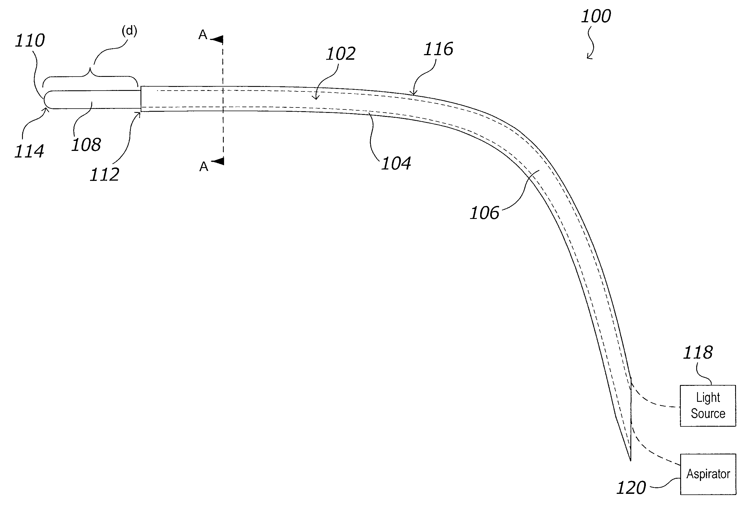
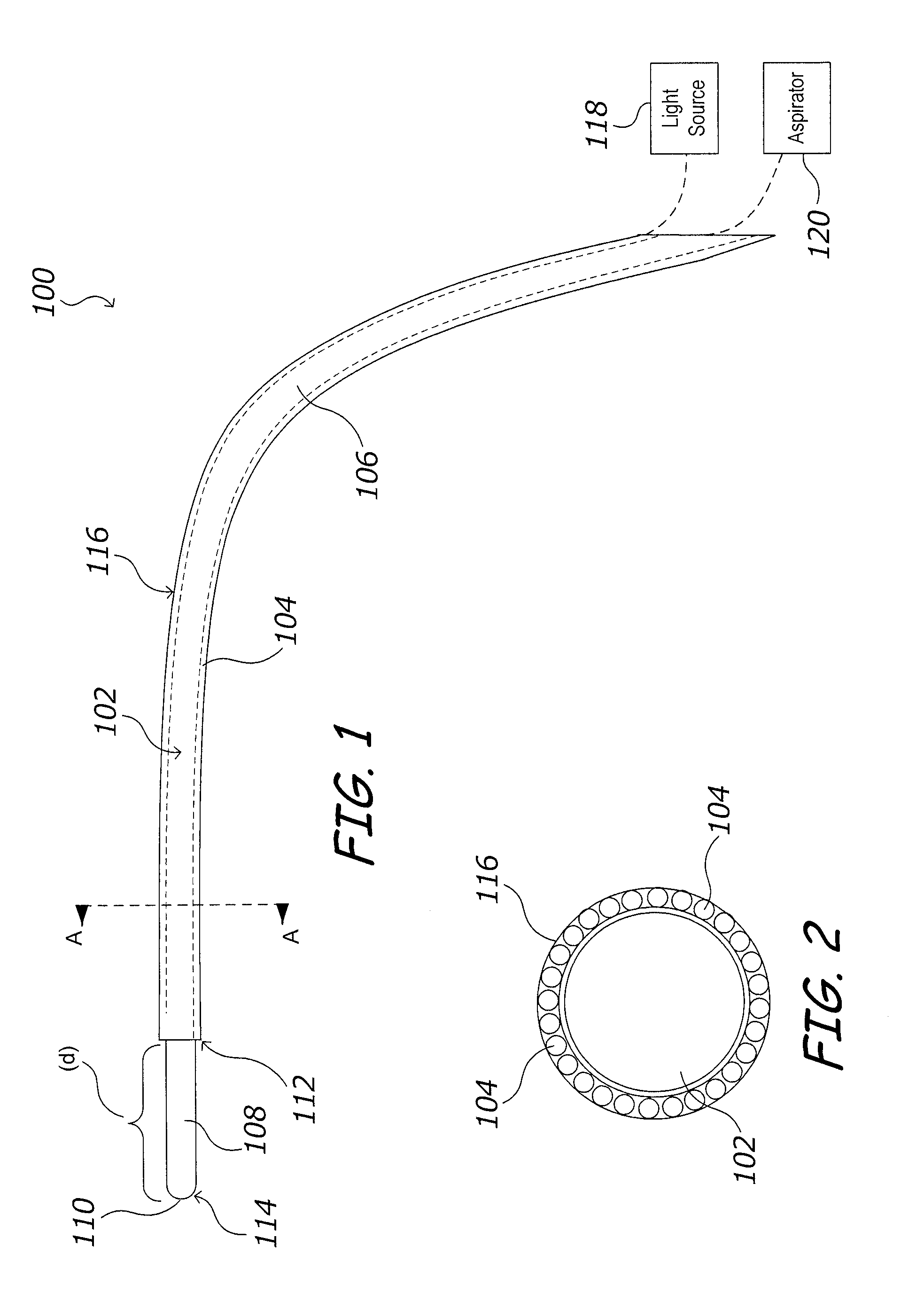
[0051]FIG. 1 depicts aspiration and illumination device 100 according to one advantageous aspect of the present invention. Aspiration and illumination device 100 generally comprises aspiration conduit 102 and optical fibers 104. As illustrated in FIG. 2 along section line AA, optical fibers 104 are positioned circumferentially about aspiration conduit 102.

[0052]Aspiration conduit 102, in one advantageous embodiment, preferably comprises a non-metallic substance such as, for example, a flexible plastic material. It is further contemplated that aspiration conduit 102 may be provided of a material that can hold a shape when deformed providing increased control for the surgeon.

[0053]As can be seen in FIG. 1, aspiration conduit 102 comprises a body portion 106 and a tip 108, the tip 108 provided with a distal end 110. In one advantageous embodiment, tip 108 is provi...


PUM


Abstract

A combination aspiration / irrigation and illumination device using optical fibers circumferentially disposed around the aspiration conduit for transmitting illuminating light to a cavity to be aspirated. The aspiration conduit having a tip that is detachably affixed to and end of the aspiration conduit. The optical fibers terminated at a distance (d) from a distal end of the tip. Also provided is an image fiber(s) for transmitting image data from the distal end of the device.

Description

CROSS-REFERENCE TO RELATED APPLICATIONS[0001]This applicaiton is a continuation-in-part of U.S. patent application Ser. No. 11 / 757,707 filed Jun. 4, 2007, which is a continuation-in-part of U.S. patent application Ser. No. 11 / 384,843 filed on Mar. 20, 2006, which claims the benefit of the filing date of U.S. Patent Application Ser. No. 60 / 663,690 filed Mar. 21, 2005.FIELD OF THE INVENTION[0002]This invention relates to a surgical instrument, more specifically this invention relates to a combination suction / irrigation device and optical device that may provide a visual indication of the area in which the tool is inserted.BACKGROUND OF THE INVENTION[0003]Minimally invasive surgery provides some significant advantages over open surgical procedures and as such, is being more frequently utilized. However, minimally invasive surgery and surgical techniques, for example, minimal incision surgery such as is utilized in spinal procedures, have created a special set of requirements with regar...

Claims


Application Information

Patent Timeline
Patent Type & Authority Applications(United States)
IPC IPC(8): A61M1/00
CPCA61B1/00105A61B1/00165A61B1/00167A61M1/008A61B19/5202A61B2019/5206A61B1/015A61B90/30A61B2090/306A61M1/84
Inventor LIEPONIS, JONAS V.
Owner LIEPONIS JONAS V
Why Eureka
Try Eureka