Anchored RF ablation device for the destruction of tissue masses

a tissue mass and ablation device technology, applied in the field of tissue mass ablation devices, can solve the problems of severely limiting the appeal of patients, cutting off the blood supply to the fibroid, shrinking of the fibroid, etc., and achieve the effect of reducing the recovery tim

Active Publication Date: 2009-09-03
AMERICAN CAPITAL +1
View PDF6 Cites 31 Cited by
  • Summary
  • Abstract
  • Description
  • Claims
  • Application Information

AI Technical Summary

Benefits of technology

[0048]As compared to a conventional hysterectomy, the present invention is directed to a device for the treatment of uterine fibroids and other tissue masses that meets the needs of women by conserving the uterus and reducing recovery time from 6-8 weeks to 3-10 days.

Problems solved by technology

This results in cutting off the blood supply to the fibroid and the shrinkage of the fibroid over time.
However, the unacceptably high rate of complications severely limits its appeal to patients.
However, due to its high rate of complications and long recovery time, this option is also not very appealing to patients.
Typical complications involve risk of infection, relatively severe post-surgical pain, damage to the uterus and other risks normally associated with such types of surgery.
Moreover, such damage may be relatively subtle and may only come to light when the uterus begins to swell in pregnancy and ruptures at a weak point created during the surgery, resulting in loss of the fetus.
However this procedure results in infertility.

Method used


Image

  • Anchored RF ablation device for the destruction of tissue masses
  • Anchored RF ablation device for the destruction of tissue masses
  • Anchored RF ablation device for the destruction of tissue masses

Examples


Embodiment Construction

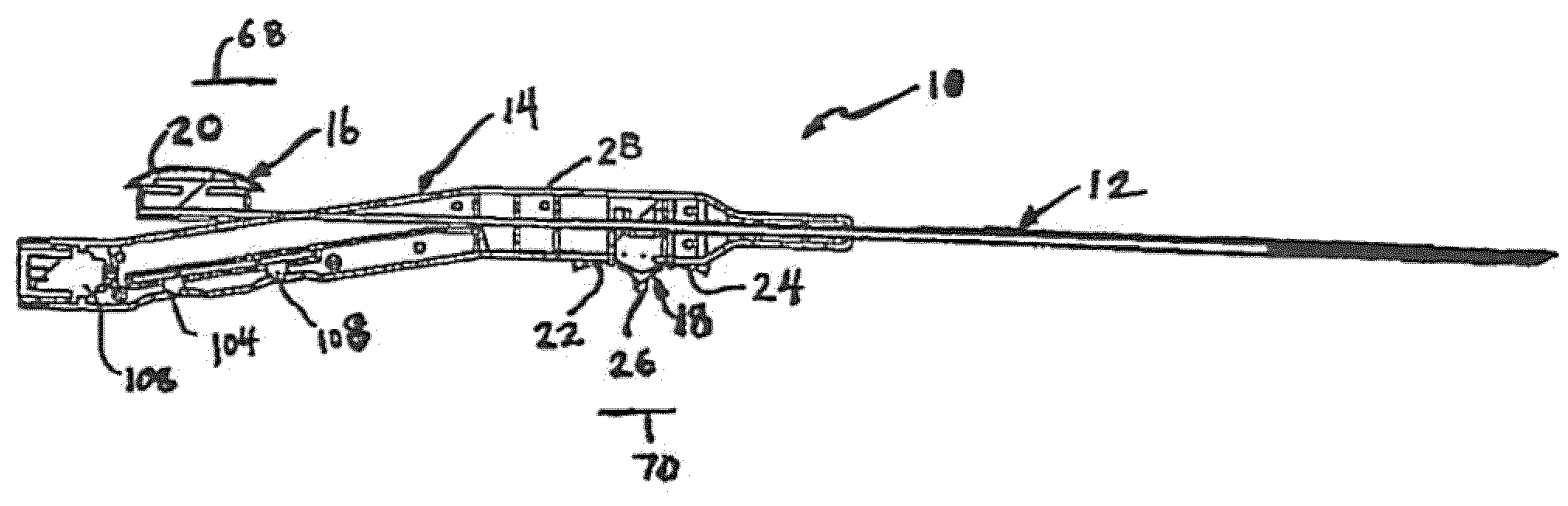
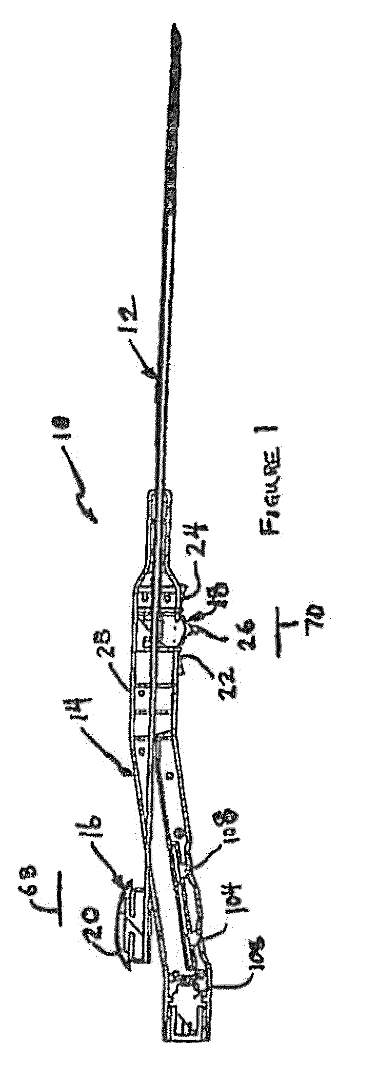
[0082]Referring to FIG. 1, an ablation instrument 10 constructed in accordance with the present invention is illustrated. Instrument 10 comprises a catheter portion 12 and a handle portion 14. Ablation instrument 10 is illustrated with one of the two mating handle halves removed and partially in cross section, in order to reveal its internal parts and workings in connection with the following description.

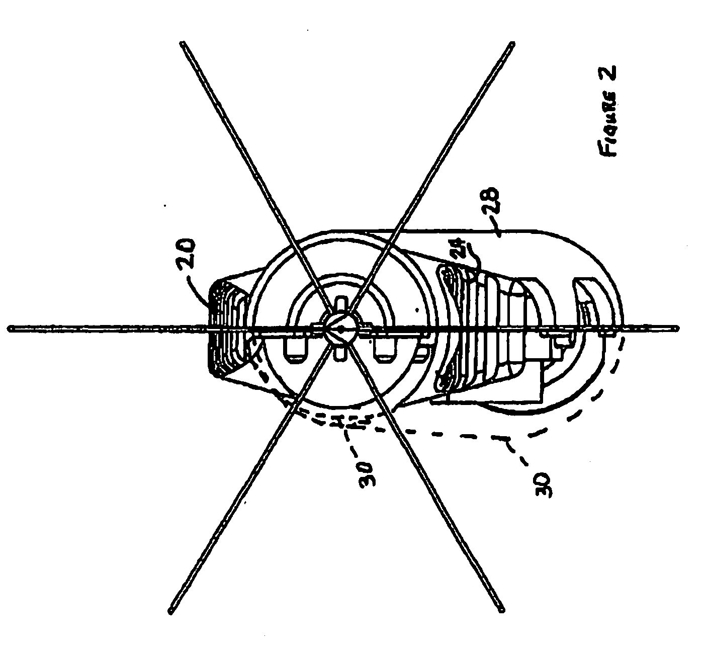
[0083]Referring to FIGS. 1 and 2, the inventive ablation instrument 10 is illustrated in the fully retracted position suitable for advancement of catheter portion 12 into tissue, for example, tissue to be subjected to ablation by being treated with radiofrequency energy. In this position, the catheter 12 present a simple thin smooth pointed surface well-suited to penetrate healthy tissue while doing minimal damage. At the same time, the sharpness of the point and the relatively stiff, though somewhat flexible, nature of catheter 12 enables accurate steering of the point and control ...


PUM


Abstract

An anchoring member which comprises a support structure and at least one anchor secured to the anchoring member is disclosed. An anchor deflection member is disposed generally externally to and at least partially surrounding and extending along the perimeter of the anchoring member. The anchor deflection member supports the anchoring member for sliding longitudinal movement in directions which result in advancement and retraction of a point on the anchor. The anchor deflection member defines a guide surface positioned on the inside of the anchor deflection member. The guide surface extends longitudinally, and it is configured and dimensioned to slidingly guide the cylindrical anchoring member. A deflection lip is positioned relatively inwardly with respect to the guide surface. The deflection lip is positioned to outwardly deflect the point of the anchor as the anchor is advanced from a position removed from the deflection lip toward the deflection lip into contact with the deflection lip and beyond the deflection lip.

Description

CROSS REFERENCE TO RELATED APPLICATION[0001]Not ApplicableBACKGROUND[0002]In the United States, approximately 230,000 women have hysterectomies annually. The primary reason for performing a hysterectomy is the presence of uterine fibroids. These fibroids grow in the wall of the uterus and may range in size up to several inches across. In the United States alone, there are more than six million women with uterine fibroid symptoms who prefer to suffer, rather than endure the risks and inconveniences associated with major surgery, especially a major surgery that results in infertility. Outside of the United States, the situation is much the same, with millions of women suffering with fibroids in need of a safe alternative to hysterectomy.[0003]Recently, another treatment option (uterine artery embolization) has been introduced. Generally, this procedure involves embolization of the arteries which feed the urine fibroid. This results in cutting off the blood supply to the fibroid and th...

Claims


Application Information

Patent Timeline
Patent Type & Authority Applications(United States)
IPC IPC(8): A61B18/18
CPCA61B17/42A61B18/1477A61B18/1487A61B2017/4216A61B2018/00279A61B2018/1475A61B2018/00595A61B2018/1425A61B2018/143A61B2018/1432A61B2018/00577
Inventor EPSTEIN, GORDONLEE, BRUCECOHEN, JEFFREY M.HAGMANN, ADAMSPERO, RICHARD
Owner AMERICAN CAPITAL
Why Eureka
Try Eureka