
Firestop block and thermal barrier system for fluted metal decks

a technology of thermal barrier system and firestop block, which is applied in fireproofing, building repairs, walls, etc., can solve the problems of higher cost of cementitous materials and intumescent materials, and achieve the effect of enhancing installation safety

Inactive Publication Date: 2009-09-10
COLON MARK
View PDF15 Cites 60 Cited by
  • Summary
  • Abstract
  • Description
  • Claims
  • Application Information

AI Technical Summary

Benefits of technology

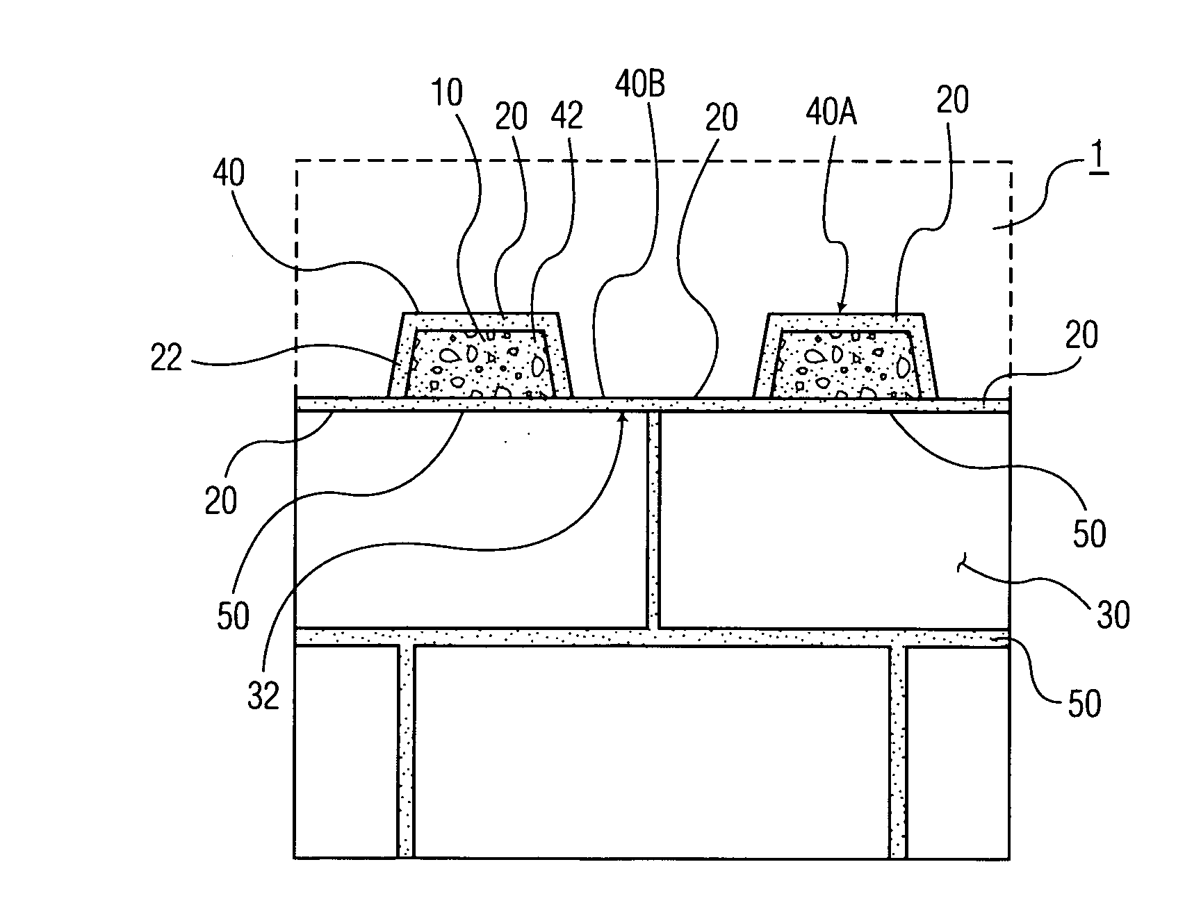
[0011]In surmounting the disadvantages of the prior art, the present invention provides a method and system for installing a thermal barrier in openings and gaps in or between building structures such as walls, ceilings and floors. In so doing, the present invention provides increased convenience, effectiveness and safety in comparison to the prior art mineral wool / coating and other methods. The thermal barriers of the present invention have the ability to conform to the openings and gap spaces between the tops of walls and fluted metal decks. The thermal barriers also have the ability to permit movement of the various building structures around the openings or gaps. In particular, protection on both sides of “head-of-wall” joint assemblies (arising between a wall and ceiling), may be conveniently accomplished by the thermal barriers and methods of the present invention.
[0015]Firestop barriers made in accordance with the above-described in-situ methods of the present invention provide excellent fire resistance and sealing ability as well as smoke and acoustic barrier properties that also provides for flexibility. They are also sufficiently strong to resist dislodgement from the gap or opening due to pressure (e.g., force from a water hose) and are highly amenable to visual inspection.

Problems solved by technology

Intumescent materials, however, may be more expensive than cementitous materials.

Method used


Image

  • Firestop block and thermal barrier system for fluted metal decks
  • Firestop block and thermal barrier system for fluted metal decks
  • Firestop block and thermal barrier system for fluted metal decks

Examples


Embodiment Construction

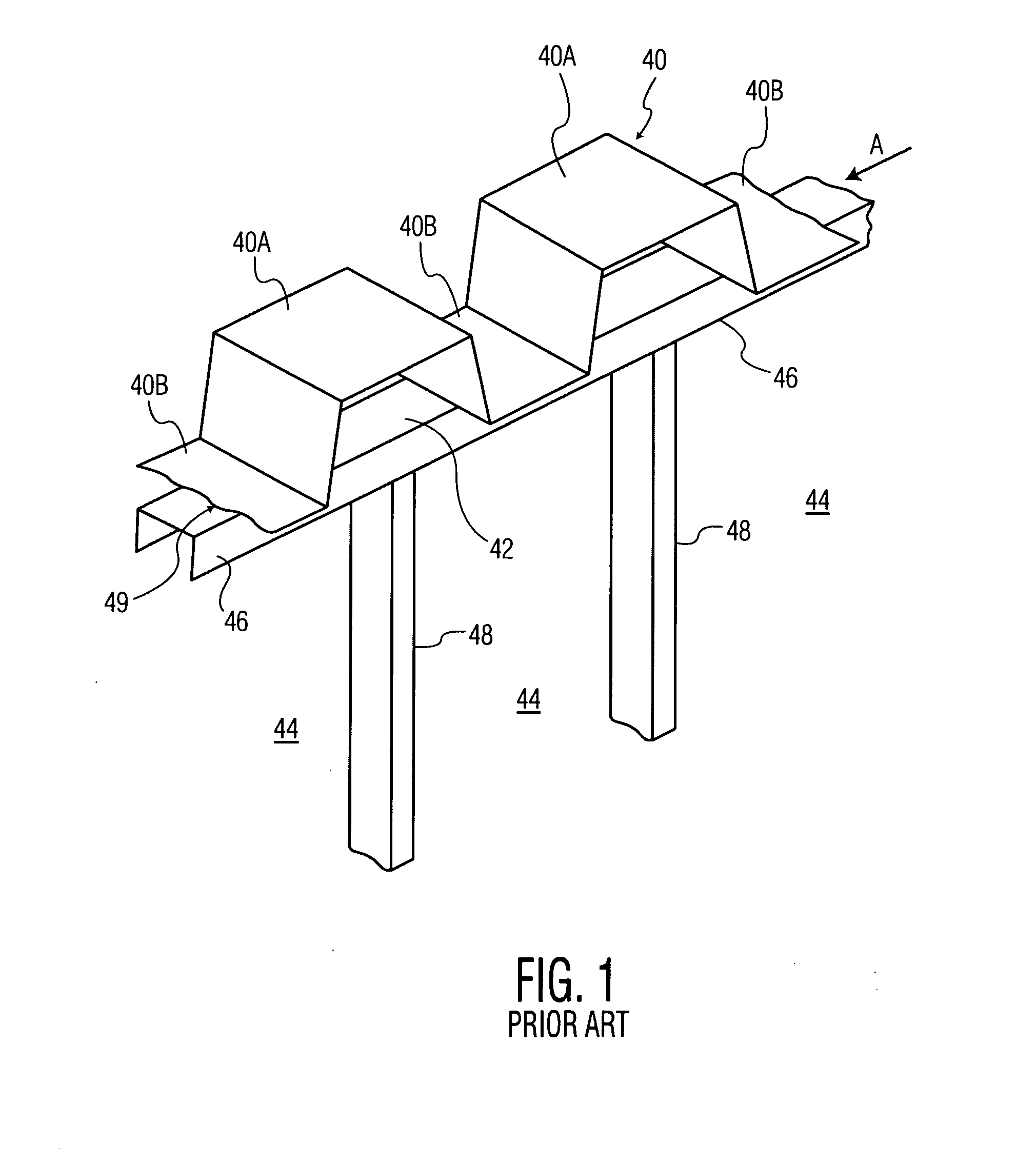
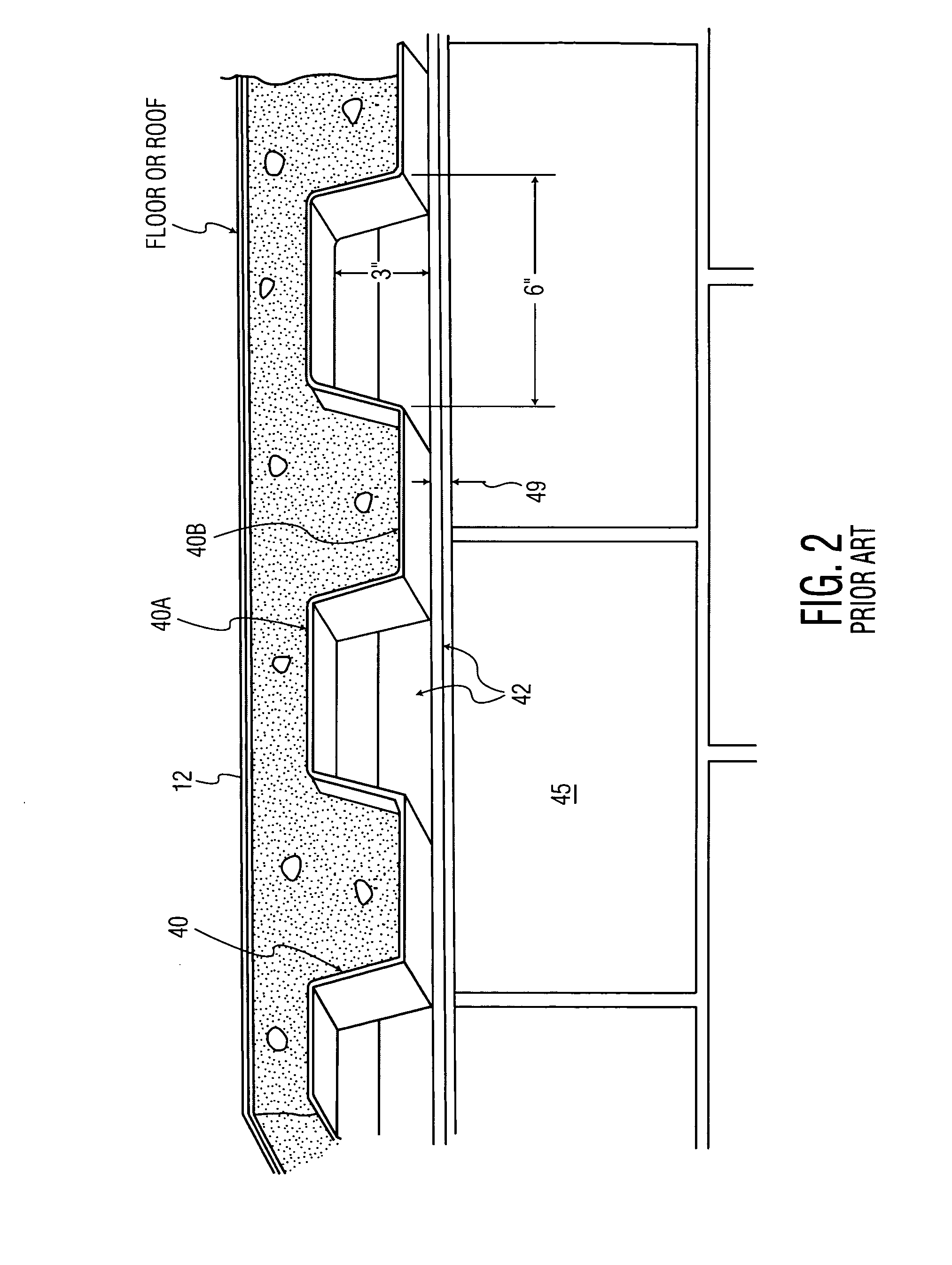
[0024]Referring now to the drawings wherein the showings are for purposes of illustrating different embodiments of the present invention and not for purposes of limiting the same, FIG. 4 perspectively illustrates a firestop block 10 configured to be slidably inserted into a fluted opening 42 (see FIG. 1) of a fluted metal deck 40.

[0025]The present invention employs one or more thermal barrier firestop blocks 10 that may be conveniently placed in openings in a structure, such as a wall, ceiling, or floor, or conveniently placed in gaps such as are defined in the joints between walls, ceilings, and / or floors. The firestop blocks are placed in the hole or joint gap formed between the head of a wall and a fluted metal deck. A flexible firestop material is introduced around the firestop block, thereby filling and sealing the space within the hole or joint gap and the fluted deck, and the filler / sealant firestop material is then allowed to harden within the hole or joint gap to provide a ...


PUM


Abstract

The invention provides methods, systems and devices for installing thermal barriers in openings or gaps in or between structures such as walls, ceilings and floors. At least one firestop block is positioned in the holes or gaps formed by the wall and a fluted metal deck of the ceiling or floor. The walls can be gypsum walls, which may have a metal track at the top or bottom, or could be block walls made of concrete or similar material. The firestop blocks are made of fire resistant material such as hydratable cement or intumescent materials. A flexible or flowable firestop material that is operative to cure or harden, such as elastomeric sealant or silicone, or hydratable cementitious slurry, is introduced into the space between the firestop block and the hole or gap, as a sealant or filler.

Description

FIELD OF THE INVENTION[0001]The present invention relates to firestop blocks and a thermal barrier system for building structures, and more particularly to thermal barriers for “head-of-wall” joint assemblies between tops of walls and ceilings or floors.BACKGROUND OF THE INVENTION[0002]Firestops are thermal barrier materials or combinations of materials used for filling gaps and openings such as in the joints between fire-rated walls and / or floors of buildings. For example, firestops can be used in walls or floors to prevent fire and smoke from passing through the gaps or openings required for cables, pipes, ducts, or other conduits. Firestops are also used to fill joint gaps that occur between walls, between a ceiling and the top of a wall (“head-of-wall” joints), and between a floor and vertical wall (“perimeter” joints).[0003]So-called “head-of-wall” joints pose a number of challenges for the firestopping industry. Walls are generally made of concrete block or other type of fire ...

Claims


Application Information

Patent Timeline
IPC IPC(8): E04B1/94E04B1/74
CPCE04B2/7409
Inventor COLON, MARK
Owner COLON MARK
Learn More