On-site land mine removal system

a land mine removal and on-site technology, applied in the direction of white arms/cold weapons, offensive equipment, transportation and packaging, etc., to achieve the effect of reducing the effectiveness of land mines, reducing or eliminating slag or burr, and high quality cuts

Inactive Publication Date: 2009-09-10
MANDERS STEPHEN M
View PDF56 Cites 56 Cited by
  • Summary
  • Abstract
  • Description
  • Claims
  • Application Information

AI Technical Summary

Benefits of technology

[0083]An apparatus for the reduction in effectiveness of land mines buried in ground may comprise a self-contained push-cart unit or a unit attached or attachable to a vehicle. A complete system would comprise a vehicle having a source of liquid, a high-pressure pump to move the liquid under high-pressure, a nozzle directing a liquid jet path for the liquid, a support for the nozzle, and nozzle being controllable to direct the liquid towards the ground while the nozzle is fixed relative to the vehicle. Again, the at least two nozzles are provided on the vehicle so that they direct the liquid towards the ground while the at least two nozzles are fixed relative to the vehicle. By fixed, it is meant that the height and orientation of the nozzles is controllable and does not waiver so significantly with vehicle movement that the path of cutting cannot be controlled within the design parameters of the cutting / demining pattern. For example, the at least two nozzles are fixed at a distance of less than one meter from the ground (e.g., 1 m, 0.8 m, 0.75 m, 0.6 m, 0.5 m, 0.4 m, 0.3 m, 0.25 m, 0.2 m, 0.1 m, 0.05 m and the like. Extensibility of the nozzles from the vehicle may be effected at least in part by water carrying tubes that bend with respect to each other, as by using rotary actuators or telescoping tubes carrying the water. The moving cart may be positioned at a location and the arms carrying the jets may be articulated to sweep over an area at a constant height or controlled and variable height to sweep and uncover mines and to deactivate the mines.
[0084]Commercially available water jet systems and nozzles may be used. Cutting various materials by means of jets of high-pressure water is a well known technique in modern manufacturing engineering. Focused jets of high-pressure water from 2,000 pounds per square inch pressure (“psi”) or less, up to 60,000 psi or more, are capable of cutting virtually any material. The term “high pressure” therefore means water pressure of at least 2,000 psi in the tip of the waterjet. Preferably the water pressure is at least 4,000 psi, at least 5,000 psi, at least 8,000, or more preferably at least 10,000 psi. Thick sheets of steel are capable of being cut by means of high-pressure water, as are much thinner sheets of soft or sticky material inconveniently cut by mechanical means. Cutting by means of water jets has several advantage including: sufficiently high quality cut providing for sharp inside corners, reduction in or elimination of slag or burr following the cutting operation (typically requiring a subsequent “deburring” operation following conventional cutting procedures), highly accurate contouring resulting in less wasted material, and water jet cutting allows the cut to be initiated at any point along the path to be cut on the workpiece.
[0085]The customary term in the field is “water jet cutting.” However, abrasive additives may be added to the stream of water comprising the jet to increase cutting effectiveness (although wear on the nozzle is likewise increased). For the cutting of metals, abrasive grit is typically added to the stream after the jet is formed but prior to the impact of the jet on the workpiece. Water jets including abrasives can accomplish the cutting of intricate slots, through cuts and curves cut in metals, glass, stone, ceramics, artificial and natural abrasives, composites and similar materials.
[0086]Fluids other than water can also be employed if materials cannot be in contact with water but cutting with a jet of fluid is still the preferred cutting technique. For economy of language we will refer herein to “water jet cutting” or “high-pressure water” and the like, not intending to exclude cutting by jets of fluid other than water, and not intended to exclude jets of fluid containing abrasive or other additives.
[0087]The typical technique for cutting by means of water jets is to mount the piece to be cut (hereinafter “workpiece”) in a suitable jig, die or other means for securing the workpiece into position. One or more water jets are typically directed onto the workpiece to accomplish the desired cutting, generally under computer or robotic control. The cutting power is typically generated by means of a single intensifier connected to the cutting head through high-pressure tubing, hose, piping, accumulators and filters. Typical units may have powers of at least 20 horsepower (“hp”), 50 hp, 250 hp up to 1000 hp.
[0088]The typical mode of water jet cutting is to employ a single water jet cutting head, but this is not an inherent limitation. A fine stream of water, typically traveling at two to three times the velocity of sound, is directed onto the workpiece. The stream of cutting fluid is typically pinhole size in diameter, but a jet slightly larger than ( 1 / 16) inch in diameter produces nearly 50 hp when concentrated. Hereinafter we will refer to workpiece and cutting tool in the singular, not intending thereby to exclude the use of a plurality of cutting heads and / or a plurality of workpieces.

Problems solved by technology

High-pressure water jets are used directly against the ground to both remove surface cover of dirt and natural or applied cover over land mines or other buried explosives, and the high-pressure water jets also cut through the mines, mine fuses, or mine detonators, disabling them in many cases or causing them to explode in other cases.

Method used


Image

  • On-site land mine removal system
  • On-site land mine removal system
  • On-site land mine removal system

Examples


Embodiment Construction

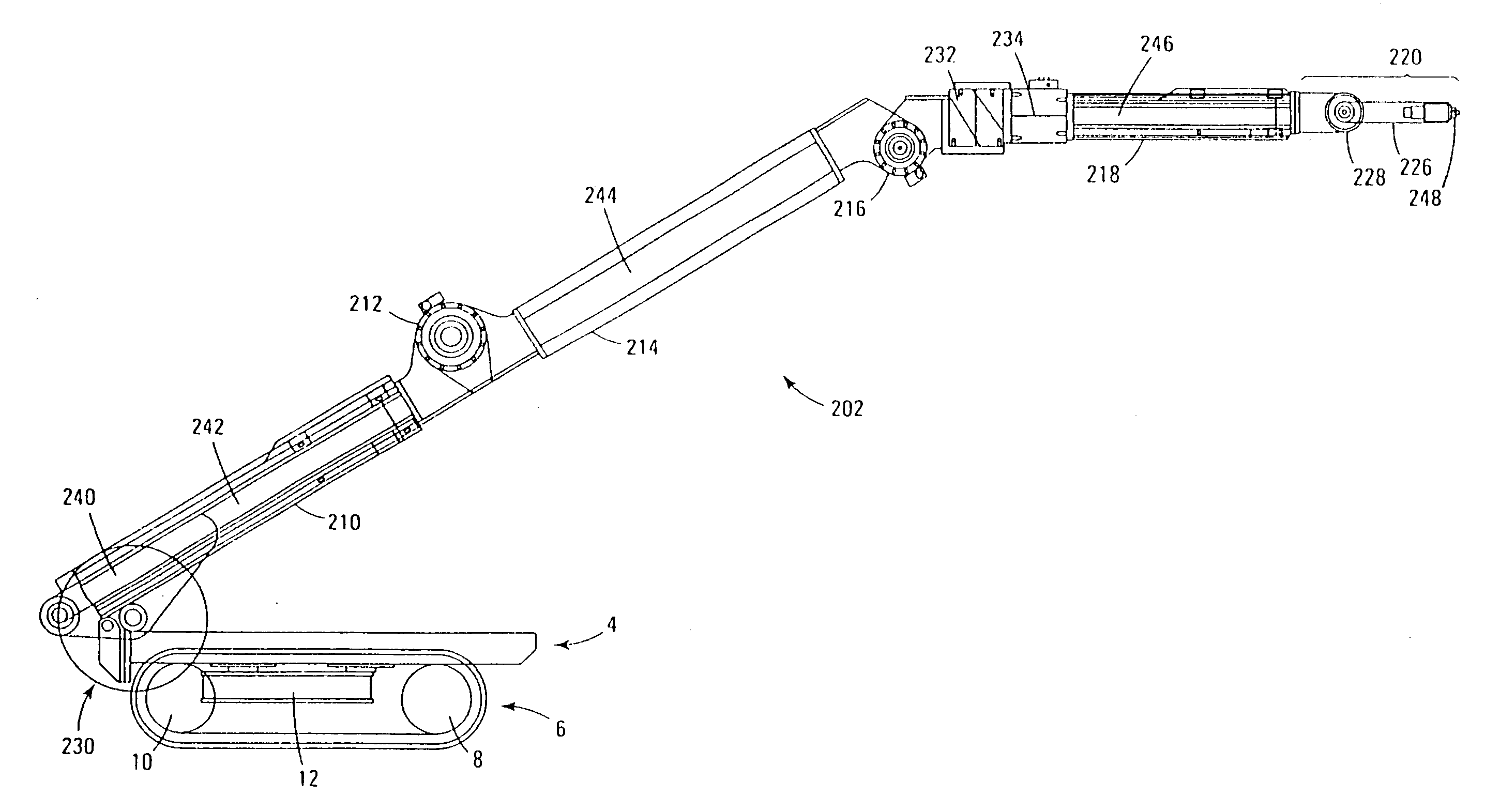
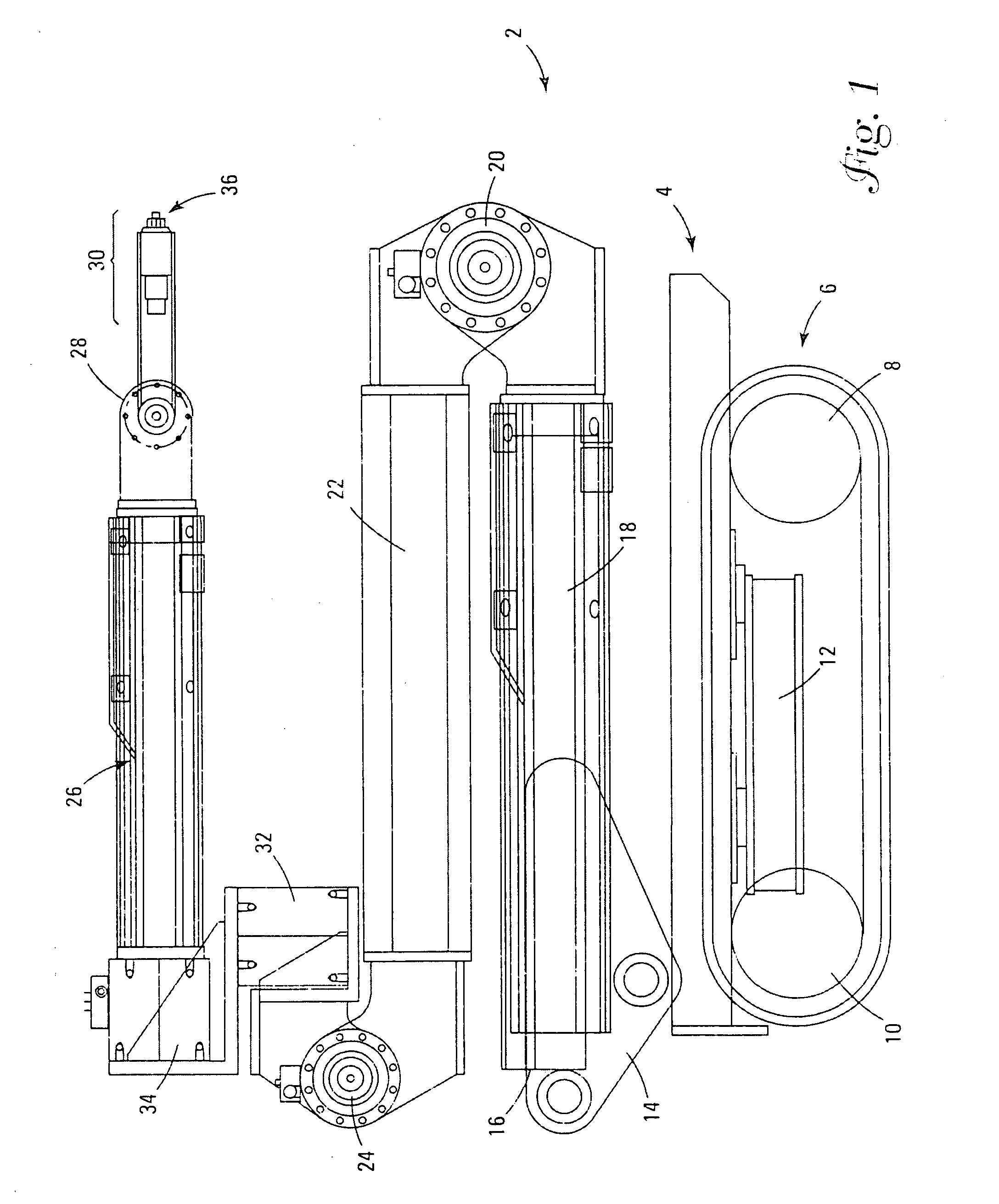
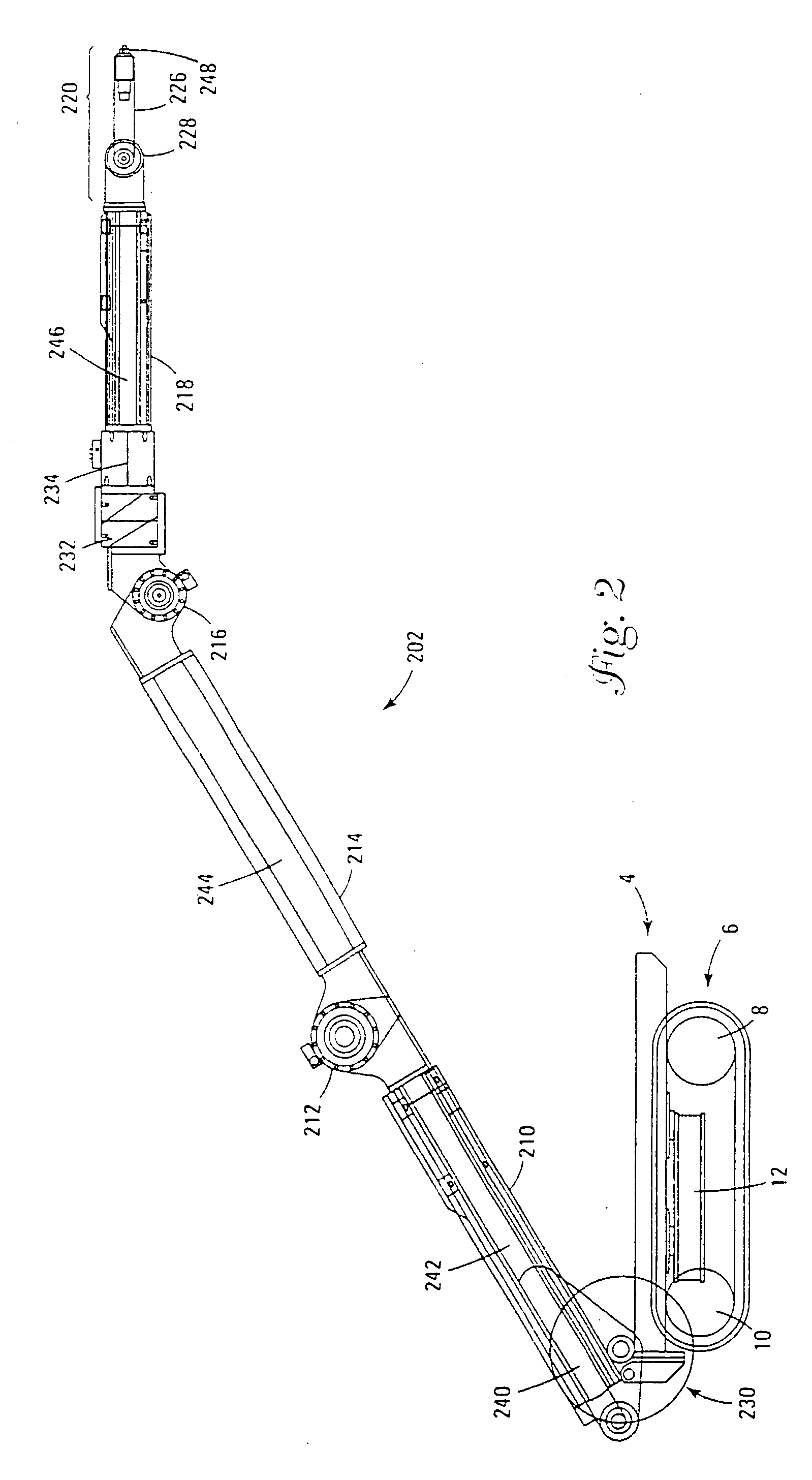
[0080]A process for the in situ and on-site deactivation of land mines comprises at least one high-pressure water jet that is directed against the ground to remove cover from the land mine and (subsequently or simultaneously) cut through the land mine, deactivating the mine or reducing its effective capability. The water jet or a series of water jets is moved over the surface area to be cleared of mines, tracing a path or series of paths that will intersect at positions that will overlap a high percentage of mines, hopefully one hundred percent of mines. If there is foreknowledge of the type of mines available or buried in an area to be cleared, the spacing or movement of the water jets may be tailored for those particular mines. If there is no basis for anticipating the specific type or size of mines present, the water jets may be spaced to assure contact with all known dimensions for mines, which is a minimum diameter of about 7.5 cm. Thus the water jets may be spaced at a minimum...


PUM


Abstract

A method of deactivating land mines buried in ground comprises projecting high-pressure water jets into ground, cutting through ground with the high-pressure water jets, and making at least one cut through a land mine or cutting through at least one land mine that had been under the ground, the cutting of the land mine reducing the performance of the land mine. The method may reduce the performance of the land mine by rendering the land mine inactive to normal detonation procedures for the land mine. To reach as many surface areas on the buried landmines, it is preferable that at least two high-pressure water jets are spaced apart are used to cut through the ground. The method may be practiced with the high-pressure water jet being carried on a vehicle and cutting is done in a line that is formed at least in part by movement of the vehicle over the ground while the high-pressure water jet is cutting ground. An apparatus for the reduction in effectiveness of land mines buried in ground may comprise a self-contained push-cart unit or a unit attached or attachable to a vehicle. A complete system could comprise a vehicle having a source of liquid, a high-pressure pump to move the liquid under high pressure, a nozzle directing a liquid jet path for the liquid, a support for the nozzle, abrasive delivery system, and nozzle being controllable to direct the liquid towards the ground while the nozzle is fixed relative to the vehicle.

Description

BACKGROUND OF THE INVENTION[0001]This invention relates generally to neutralization of explosive devices, such as land mines, unexploded ordnance (UXO), bombs, and the like. More particularly, the present invention relates to a system for neutralizing an explosive device on-site with controlled collateral damage, the system including both neutralizing components, conveying components, sensing components, motivating components, and an integrated system.[0002]Various explosive devices have been and may continue to be deployed around the world. These explosive devices are present in various forms and provide various threats to people, vehicles, livestock, and other property that may be near such explosive devices. For example, explosive devices may include anti-personnel or anti-vehicle land mines. In addition, unexploded ordinance (UXO) may be located near, and present a threat to, people and property. Examples of UXO include various ammunition such as aerial bombs, or shells, which m...

Claims


Application Information

Patent Timeline
Patent Type & Authority Applications(United States)
IPC IPC(8): F41H11/12
CPCF41B9/0031F41B9/0087F41H11/32F42D5/04F42B33/062
Inventor MANDERS, STEPHEN M.
Owner MANDERS STEPHEN M
Why Eureka
Try Eureka