

Gas introducing structure of intake path
a technology of gas introducing structure and intake path, which is applied in the direction of air intake for fuel, combustion air/fuel air treatment, machines/engines, etc., can solve the problems of uneven mixing of intake air and intake air, difficulty in uniform diffusion, and uneven recirculation of exhaust gas
- Summary
- Abstract
- Description
- Claims
- Application Information
AI Technical Summary
Problems solved by technology
Method used
Image

Examples
first embodiment
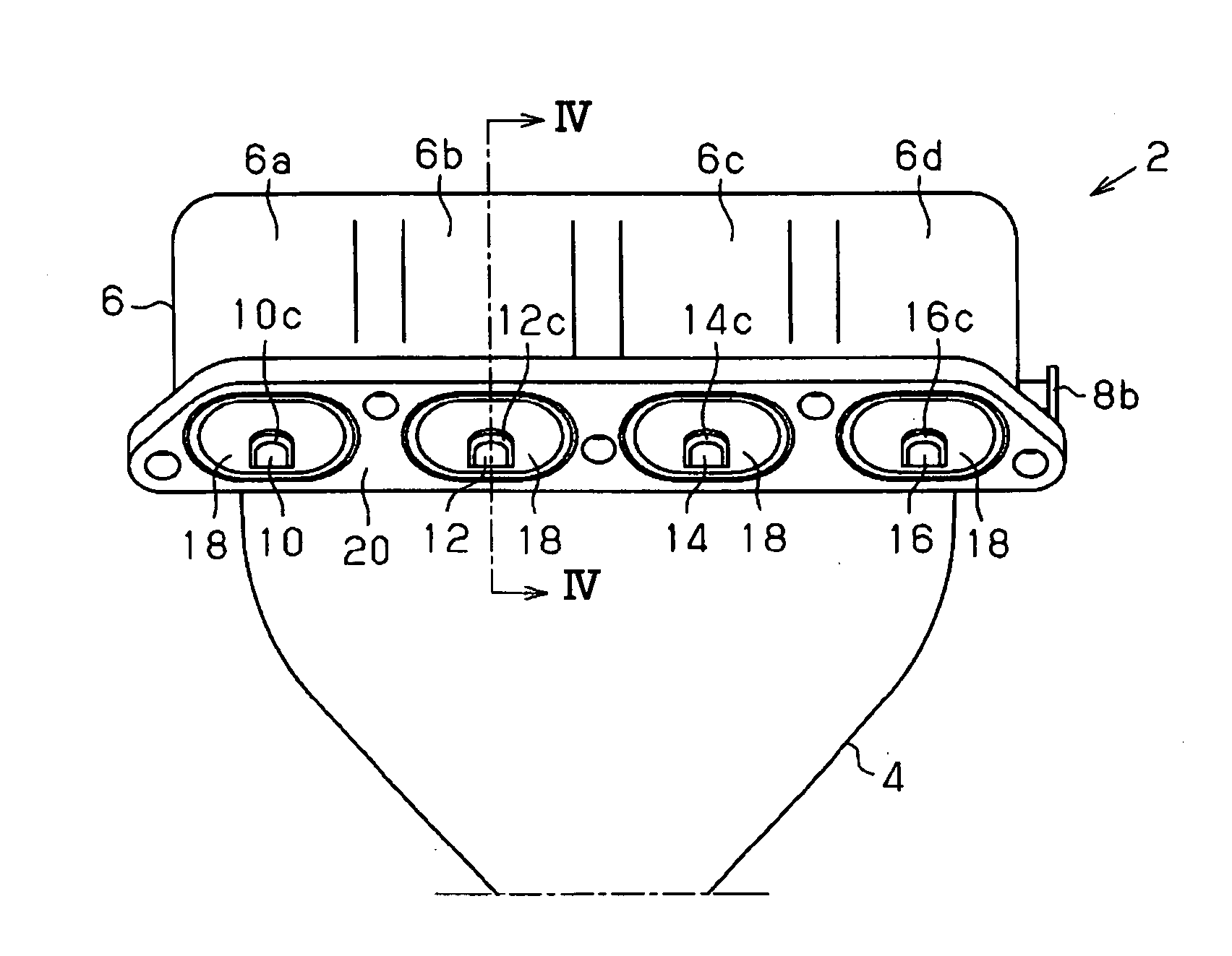
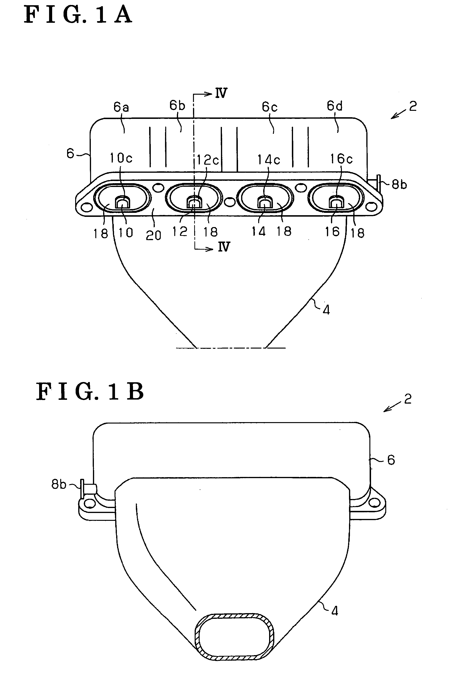
[0023]FIGS. 1 to 3 show main sections of an intake manifold 2, to which the invention is applied, in an internal combustion engine. FIG. 1A is a front view and FIG. 1B is a back view. FIG. 2A is a left side view, FIG. 2B is a right side view and FIG. 3 is a perspective view. FIG. 4 is a cross section taken along a line IV-IV in FIG. 1A.
[0024]The intake manifold 2 includes a common intake path 4 serving as a surge tank, and introduces intake air from a throttle valve via the common intake path 4. The intake manifold 2 further includes an intake branch pipe assembly 6 at a downstream of the common intake path 4. The common intake path 4 and the intake branch pipe assembly 6 are integrally molded with resin. In these figures, an overall shape of the intake manifold 2 is shown without providing a rib or the like for purposes of clarity. However, various kinds of reinforcing ribs, through holes for installing an intake air temperature sensor and the like, various kinds of engaging portio...
second embodiment 2
[0043]FIGS. 6a, 6b, 6c and 6d are longitudinal cross sections of the exhaust introducing path according to a second embodiment. Configurations of the exhaust introducing path, other than those shown in these figures, are similar to that of the first embodiment.
[0044]In an inner peripheral surface of an exhaust introducing path 110 shown in FIG. 6A, unlike the first embodiment, a configuration made of the curved wall surface and the bottom surface does not exist. The inner peripheral surface of the exhaust introducing path 110 has a rectangular shaped cross section, which is made of a ceiling 110a, side surfaces 110b and 110c, and a bottom surface 110d. The cross section may be formed in a trapezoid in which width of the ceiling 110a is narrower than that of the bottom surface 110d. Adversely, the trapezoid may be formed in a manner that the width of the bottom surface 110d may be narrower than the ceiling 110a. Further, the side surfaces 110b and 110c do not have to have an identica...
third embodiment
[0057]In a third embodiment, an example of the configuration of a connecting portion, in which the exhaust supply portion 8b (connecting portion) shown in FIGS. 2 and 4 connects with the exhaust supply pipe (gas supply pipe), will be described. Other configurations are similar to those of the first and second embodiments.
[0058]As shown in FIG. 10, the intake manifold incorporated into the internal combustion engine is connected with the exhaust supply pipe 200 of the EGR system. Specifically, a flange 200a of the exhaust supply pipe 200 is fastened with a flange 8d of the exhaust supply portion 8b with bolts.
[0059]However, an inner diameter D1 of the exhaust supply pipe 200 is smaller than an inner diameter D2 of the exhaust supply portion 8b. Further, an inner peripheral portion 8e of the flange 8d is chamfered.
[0060]According to the third embodiment described above, the following effects are achieved.
[0061](1) The inner diameter D2 of the exhaust supply portion 8b is larger than t...
PUM
 Abstract
Description
Claims
Application Information