Safety device for detecting inadequate electric braking and commutation to a safety brake

a safety device and electric braking technology, applied in the direction of motor/generator/converter stopper, dynamo-electric converter control, stopping arrangement, etc., can solve the problem of excessive adhesion and achieve the effect of less stress

Active Publication Date: 2009-09-10
ALSTOM TRANSPORT TECH SAS
View PDF6 Cites 38 Cited by
  • Summary
  • Abstract
  • Description
  • Claims
  • Application Information

AI Technical Summary

Benefits of technology

[0010]placing less stress on the safety brake by using it

Problems solved by technology

However, this device has one disadvantage: the force/speed characteristic thereof is dependent only on the characteristics of the motor and the value of the braking resistance selected, it cannot theref

Method used


Image

  • Safety device for detecting inadequate electric braking and commutation to a safety brake
  • Safety device for detecting inadequate electric braking and commutation to a safety brake
  • Safety device for detecting inadequate electric braking and commutation to a safety brake

Examples


first embodiment

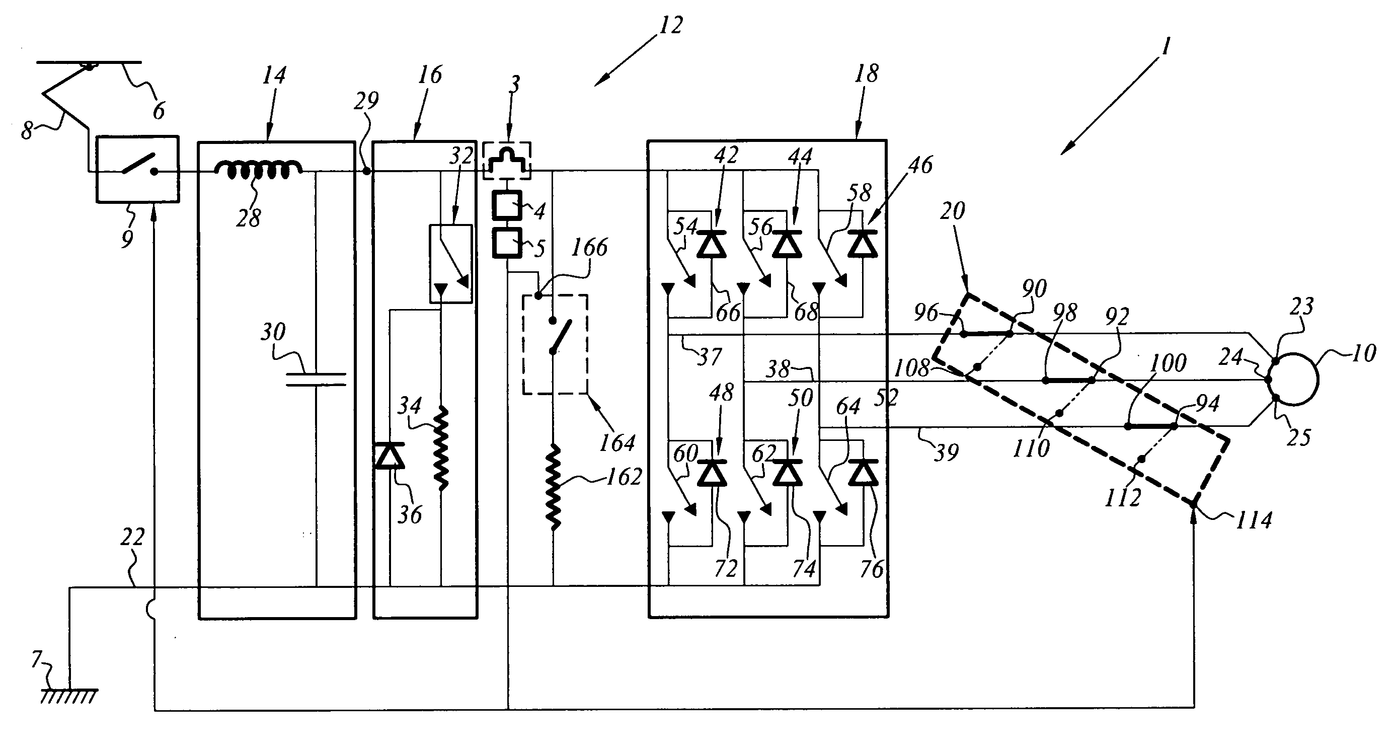
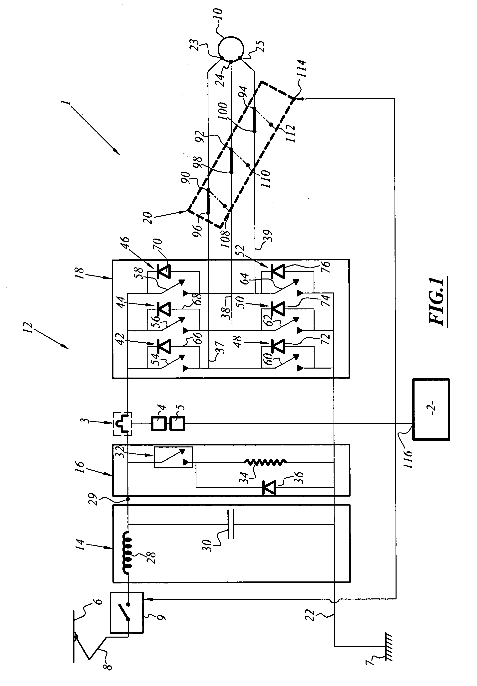
[0050]FIG. 1 illustrates a braking system which is referred to as a safety braking system and which is associated with an electric traction chain 1 of a rail vehicle.

[0051]The braking system comprises a first electric service brake which is integrated in the electric traction chain 1 and a second safety brake 2 which is in this instance mechanical.

[0052]The braking system also comprises a device 3 for monitoring the braking performance of the first brake using current intensity measurement data, a detection device 4 which is capable of reaching the decision to commutate from the first brake to the second brake when a predetermined threshold value is exceeded by the intensity measurement data and a device 5 for transmitting a commutation command.

[0053]The traction chain 1 is supplied with electrical power by means of a catenary line (or a third rail) 6 which is under high voltage and which is referenced by a ground 7 which is connected to the earth.

[0054]The electric traction chain 1...

second embodiment

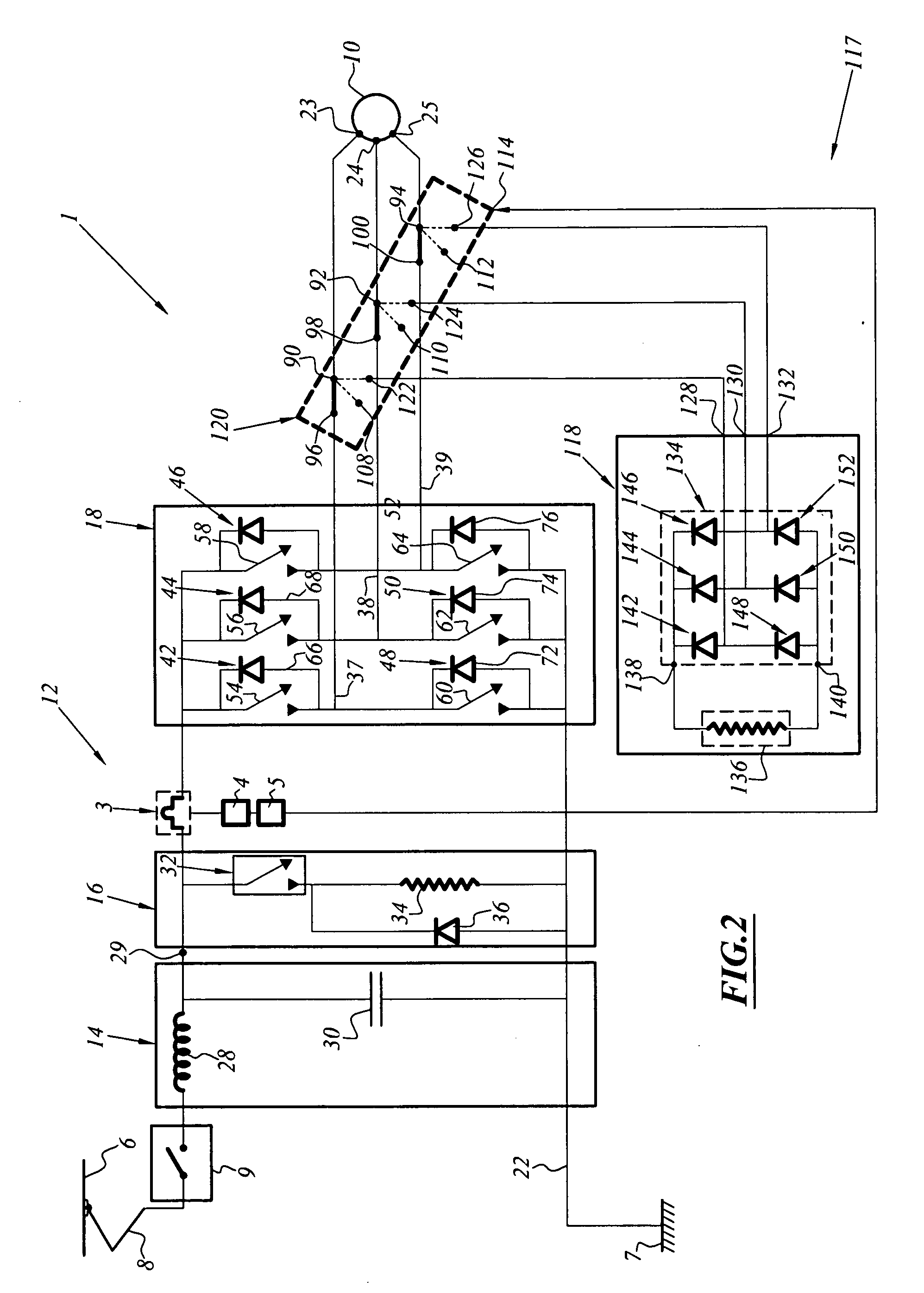
[0093]FIG. 2 illustrates a safety braking system associated with a traction chain 1, which is identical to that described in FIG. 1.

[0094]Only the safety brake 2 is different and in this instance is an electric brake 117 which comprises a braking torque production device 118 and the electromechanical commutator 20 which in this instance is an electromechanical commutator 120 comprising a third group of output pins 122, 124, 126 which are connected to inputs 128, 130, 132 of the braking torque production device 118, respectively.

[0095]The second electric brake 117 comprises the generator 10, the electromechanical commutator 120 and the braking torque production device 118.

[0096]The electromechanical commutator 120 is capable of disconnecting the input terminals 23, 24, 25 of the motor from the output lines 37, 38, 39 of the inverter 18 by commutating electric contacts of the first group of pins 96, 98, 100 to the second group of output pins 108, 110, 112 and thus isolating the motor ...

third embodiment

[0103]FIG. 3 represents a safety brake system associated with a traction chain 1 identical to that of FIGS. 1 and 2.

[0104]Compared with the system described in FIG. 1, the second brake in this instance is an electric brake comprising the free wheel diode bridge 66, 68, 70, 72, 74, 76 of the inverter 18, a terminal load resistor 162, an auxiliary electromechanical relay 164 which is connected in series to the resistor 162 and controlled at an input 166, the assembly comprising the relay 164 and the resistor 162 being interposed between the chopper 16 and the inverter 18.

[0105]The second electric brake also comprises an auxiliary circuit, which is not illustrated in this instance in FIG. 3, and which is capable of inhibiting the commands for the power transistors of the inverter 18 to be placed in a conductive state.

[0106]The assembly of the devices 3, 4, 5 is similar to that of FIG. 1.

[0107]In this instance, however, the output of the transmission device 5 or output of the current re...


PUM


Abstract

A device is provided for detecting inadequate electric braking and commutation to a safety brake is intended for a vehicle with electric traction, in particular a rail vehicle, which is provided with a traction chain, the system including a first electric, non-safety brake which is integrated in the traction chain and a second safety brake.
The device includes a member for commutation from the first brake to the second brake, a device for monitoring the braking performance of the first brake using data for measurement of the intensity of a current, a decision device for commutating from the first brake to the second brake when a predetermined threshold value is exceeded and a device for transmitting a commutation command to the at least one commutation member.

Description

[0001]This claims the benefit of FR 07 57341 filed on Sep. 4, 2007 and hereby incorporated by reference herein.[0002]The invention relates to a device for detecting inadequate electric braking and commutation to a safety brake. It is intended for a vehicle which is electrically driven, for example, a rail vehicle.BACKGROUND OF THE INVENTION[0003]A safety braking system ensures the desired braking force is produced in an extremely reliable manner.[0004]In the field of rail transport, there are principally two types of braking operation: service braking and emergency braking.[0005]The service braking operation is the one which is most commonly used during operation. It can be adjusted between a minimum force value close to 0 and a maximum force value. It can be broken down itself into a plurality of modes, depending on the trains: purely electric brake, purely mechanical brake or combined electric and mechanical brake. It carries out all the “normal” stopping and deceleration operatio...

Claims


Application Information

Patent Timeline
IPC IPC(8): H02P3/22
CPCB60L3/0076B60L7/003B60L7/06B60L2200/26H02P6/24Y02T10/642B60L7/22H02P3/22Y02T10/64B61H9/00B61H11/00
Inventor JOBARD, THIERRY
Owner ALSTOM TRANSPORT TECH SAS
Why Eureka
Try Eureka