Phase-Shift Analysis System and Method

a phase shift analysis and phase shift technology, applied in the field of borescopes and endoscopes, can solve the problems of time-consuming, indirect dimensional measurement, and insufficient information to produce a full 3d surface map

Active Publication Date: 2009-09-10
BAKER HUGHES INC
View PDF14 Cites 62 Cited by
  • Summary
  • Abstract
  • Description
  • Claims
  • Application Information

AI Technical Summary

Problems solved by technology

This leads to difficulties in directly determining dimensional measurements, especially in three spatial dimensions.
Stereo methods can be used to create a 3D view, but can only provide information where two points on the image can be correlated.
This can be problematic when little surface detail exists.
The correlation process can also require significant processing, so producing a full 3D surface map can be time consuming.
However, the areas between the dots are left to be interpolated, so any surface variations between them are lost.
Finally, a single line profile provides useful information along that single profile, but proper positioning of the single line on the object of interest can be difficult, and measurements that require non co-linear points, such as point to line or area

Method used


Image

  • Phase-Shift Analysis System and Method
  • Phase-Shift Analysis System and Method
  • Phase-Shift Analysis System and Method

Examples


Embodiment Construction

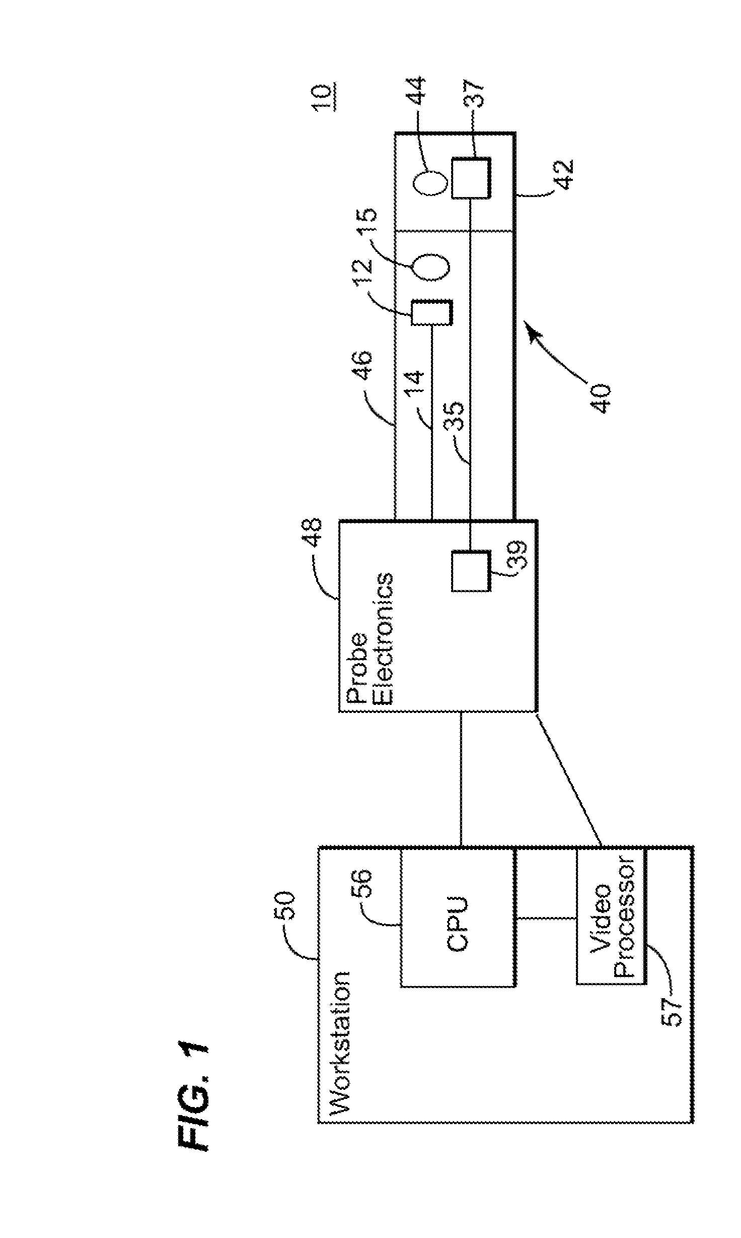
[0027]Illustrated in FIG. 1, a borescope / endoscope system 10 according to an embodiment of the invention is shown. An insertion tube 40 comprises elongated portion 46 and detachable tip 42. Distal tip 42 contains viewing optics 44 which is used in combination with probe optics 15 to guide and focus light from the surface or object (not shown) onto imager 12. The viewing optics may optionally include relay optics such as a lens or fiber optic system to remote the camera head away from the distal tip.

[0028]Imager 12 is included at the end of elongated portion 46 that is typically flexible, though it could be located proximally in other embodiments using a relay lens system or coherent fiber bundle to carry the image from the distal end to the proximal imager. Imager 12 may comprise, for example, a two-dimensional array of light-sensitive pixels that outputs a video signal in response to the light level sensed at each pixel. Imager 12 may comprise a charge-coupled device (CCD), complem...


PUM


Abstract

A system for determining an object distance z includes a plurality of light emitters. A group of at least one of the plurality of light emitters includes an emitter group, and the pattern projected when one emitter group is emitting includes a fringe set. The light pattern of one fringe set exhibits a phase-shift relative to the light patterns of the other fringe sets, and the phase-shift varies as the distance from the origin of the plurality of fringe sets varies. The system further includes a processing unit that is configured to compute a ripple metric value associated with each of a plurality of possible z values. The processing unit is further configured to determine an approximated z value using the computed ripple metric values. A probe system is also provided. The probe system is configured to project a plurality of fringe sets from the probe onto an object. The light pattern of one fringe set exhibits a phase-shift relative to the light patterns of the other fringe sets, and the phase-shift varies as the distance from the origin of the plurality of fringe sets varies. The probe system is further configured to compute a ripple metric value associated with each of a plurality of possible z values, where z is an object distance. The probe system is also configured to determine an approximated z value using the computed ripple metric values. A method for determining an object distance z is also provided.

Description

BACKGROUND OF THE INVENTION [0001]1. Field of the Invention[0002]The subject matter described herein relates generally to borescopes and endoscopes, and more particularly, to a borescope / endoscope which uses phase-shift analysis to provide 3D surface mapping and dimensional measurement.[0003]2. Related Art[0004]Borescopes and endoscopes are typically used for inspection inside a remote cavity, Most borescopes / endoscopes, referred to herein as a probes, employ an external light source coupled to fiber optic bundles in the probe to provide illumination of a remote object or surface at the distal end. When the object is illuminated, an internal image is formed by a lens system on an image sensor, and the image is relayed to a connected display, such as a video screen. The image sensor may be located at the proximal end of the probe, as with an optical rigid borescope or fiberscope, or at the distal end as with a video borescope or endoscope. Such systems are often used to inspect in in...

Claims


Application Information

Patent Timeline
IPC IPC(8): G01B11/00
CPCG02B23/2407G01B11/25
Inventor BENDALL, CLARK ALEXANDERHARDING, KEVIN GEORGESONG, GUIJUTAO, LI
Owner BAKER HUGHES INC
Why Eureka
Try Eureka