Transmitter

Active Publication Date: 2009-09-10
RENESAS ELECTRONICS CORP
View PDF3 Cites 16 Cited by
  • Summary
  • Abstract
  • Description
  • Claims
  • Application Information

AI Technical Summary

Benefits of technology

[0057]According to the above embodiment, a condition for minimizing the carrier leakage associated with the first modulator (1) can be achieved at a time when in the calibration action for the first modulator (1), the phase comparator (11) produces the predetermined detection state (VM) and then the controller stops changing the ratio of DC biasing currents to the first pair of transistors. Further, a condition for minimizing the carrier leakage associated with the second modulator (2) can be achieved at a time when in the calibration action for the second modulator (2), the phase comparator (11) produces the predetermined detection state (VM) and then

Problems solved by technology

The solution of using a filter to attenuate sidebands of high levels is a very simple and low-power measure, however it is hard to materialize such filter and a physically large off

Method used


Image

  • Transmitter
  • Transmitter
  • Transmitter

Examples


Embodiment Construction

1. Summary of the Preferred Embodiments

[0046]The preferred embodiments of the invention hereby disclosed will be outlined first. Here, the reference numerals and characters to refer to the drawings, which are accompanied with paired round brackets, only exemplify what the concepts of constituents referred to by the numerals and characters contain.

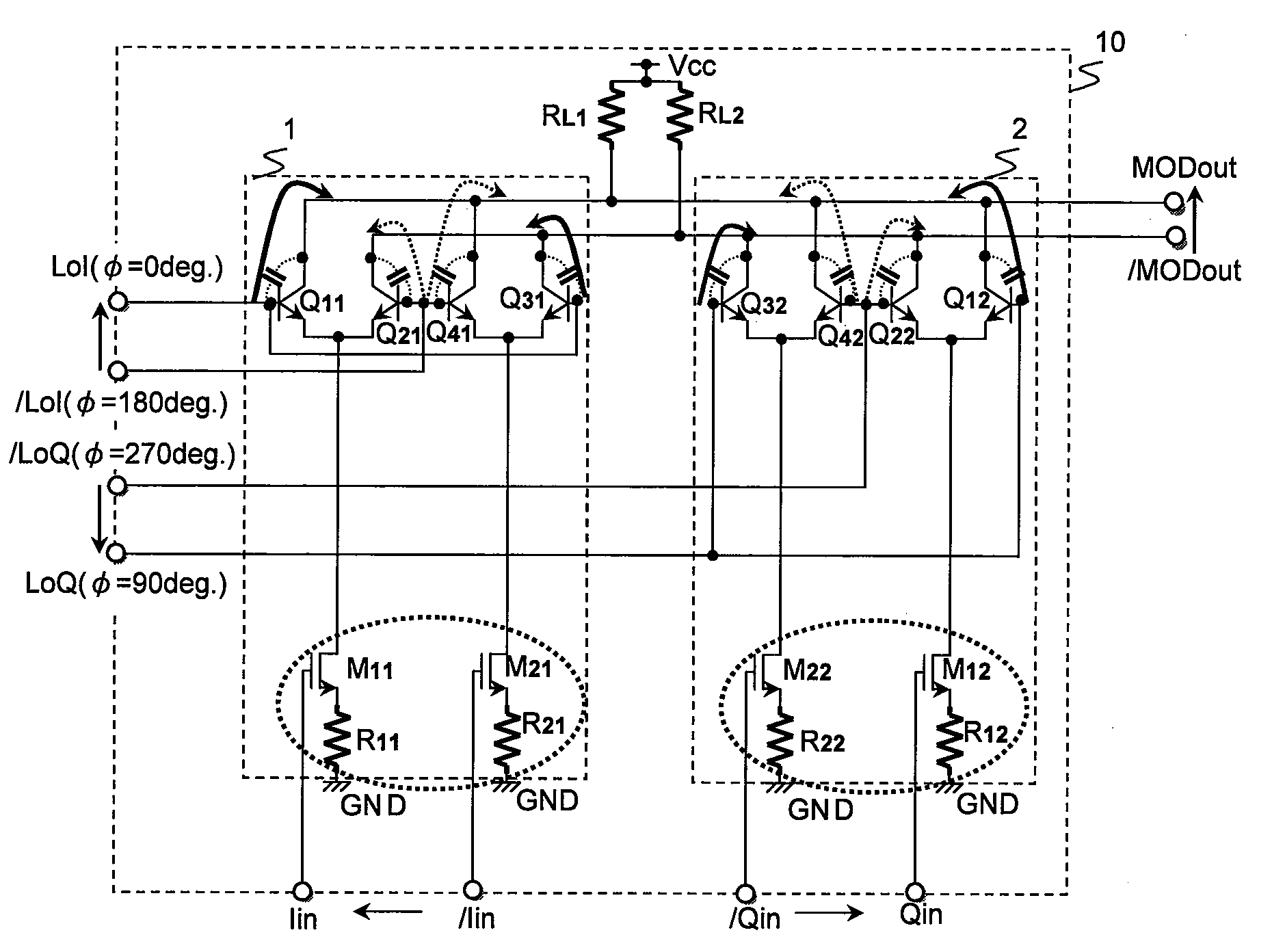
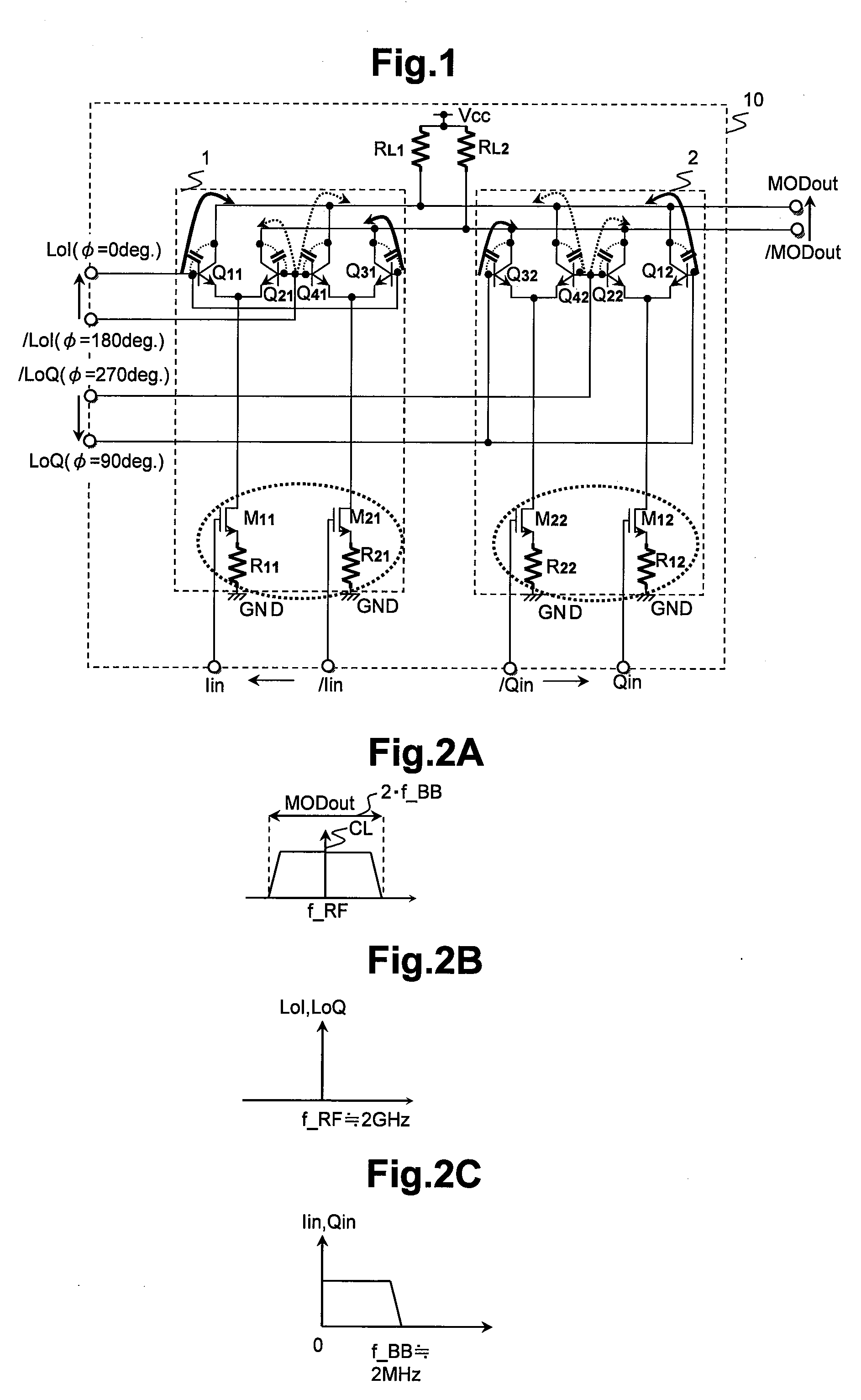
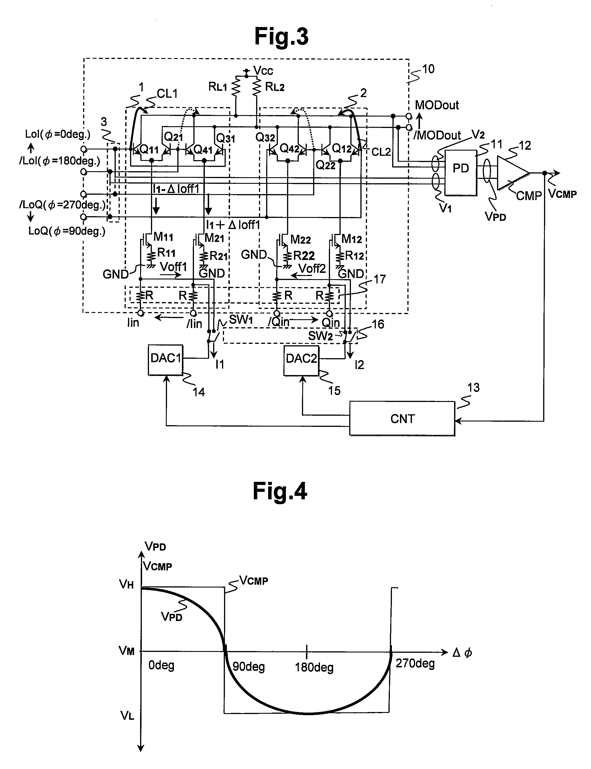
[0047][1] A transmitter according to a preferred embodiment of the invention has: a transmission modulator (10) including a first modulator (1) and a second modulator (2); a phase comparator (11); and a controller (13).

[0048]At a time of transmission, the first modulator (1) is supplied with a pair of a first non-inverted baseband signal (Iin) and a first inverted baseband signal ( / Iin), and a pair of a first non-inverted local signal (LoI) and a first inverted local signal ( / LoI).

[0049]On the other hand, at the time of transmission, the second modulator (2) is supplied with a pair of a second non-inverted baseband signal (Qin) and a second...


PUM


Abstract

The transmitter has a transmission modulator including first and second modulators, a phase comparator and a controller. First and second non-inverted local signals supplied to the modulators are set to have a predetermined phase difference. In a calibration action for reducing carrier leakage, the phase comparator is supplied with the first or second local signals, and carrier signals leaking at an output of the transmission modulator. The controller keeps changing the ratio of DC biasing currents to paired transistors of each modulator until the predetermined phase difference is detected with the phase comparator. When the predetermined phase difference is detected, the controller stops changing the ratio of DC biasing currents. The invention contributes the reduction in the chip footprint of a transmitter on the direct up-conversion (DUC) architecture, and the decrease in carrier leakage owing to local signals supplied to the transmission modulator.

Description

CLAIM OF PRIORITY[0001]The Present application claims priority from Japanese application JP 2008-054217 filed on Mar. 5, 2008, the content of which is hereby incorporated by reference into this application.FIELD OF THE INVENTION[0002]The present invention relates to a transmitter used in RF communication for mobile phones, wireless LANs and the like, and particularly it relates to a technique useful for reducing the interference by RF signals with local signals supplied to a modulator for transmission.BACKGROUND OF THE INVENTION[0003]The ubiquitous coverage that wireless communication can be held anywhere in the world, which is an ability of communication terminal equipment, such as mobile phone terminals, has been not a reality today, but under development.[0004]Such mobile systems include GSM, GPRS, EDGE, WCDMA, DCS and PCS cellular systems. As to the characteristics of these systems, the demands for multiband and multimode systems, which are arranged by widespread combinations of...

Claims


Application Information

Patent Timeline
IPC IPC(8): H04L27/00H04B1/02H04B1/04H04L27/20H04L27/36
CPCH03D7/1433H04B1/0475H04B2001/0491H04L27/0014H04L27/34H03D2200/009H04L2027/0018H03D7/145H03D7/1458H03D2200/0043H04L27/362
Inventor TOYOTA, KENJIHIKASA, KAZUHIKO
Owner RENESAS ELECTRONICS CORP
Why Eureka
Try Eureka