
Highly Optimized Digital IQ Transmitter Chain

a transmitter chain, high-efficiency technology, applied in the direction of pulse technique, code conversion, modulation, etc., can solve the problems of w-cdma, w-cdma multiple access, and other protocols such as w-cdma, which have requirements that are difficult to achieve, and respective requirements that are extremely difficult to meet in mass production or require incredible alignment efforts, in regard to implementation and efficiency under iq modulation

Active Publication Date: 2009-09-10
APPLE INC
View PDF4 Cites 25 Cited by
  • Summary
  • Abstract
  • Description
  • Claims
  • Application Information

AI Technical Summary

Problems solved by technology

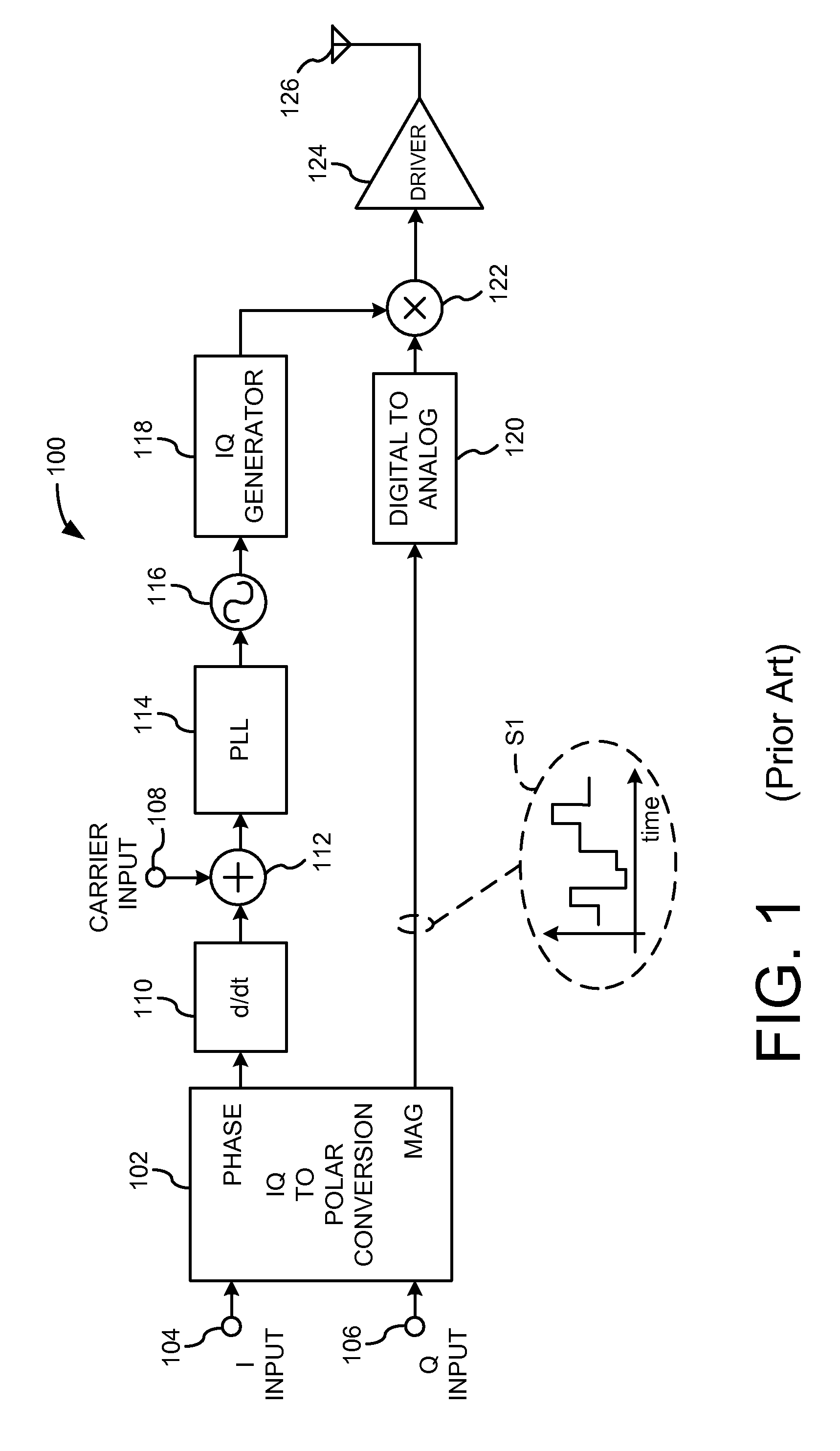
Multi-modal radios and other wireless devices present their own challenges in regard to the foregoing paradigm.
One challenge in using polar modulation architecture is establishing and maintaining proper synchronism between the phase and magnitude signals.
However, other protocols such as W-CDMA (i.e., Wideband Code Division Multiple Access) have requirements that are difficult to achieve.
Other system protocols, such as WLAN (i.e., Wireless Local Area Network—IEEE 802.11 standard) or WiMax, have a bandwidth greater than 5 MHz and the respective requirements are extremely difficult to fulfill in mass production or necessitate incredible alignment efforts.
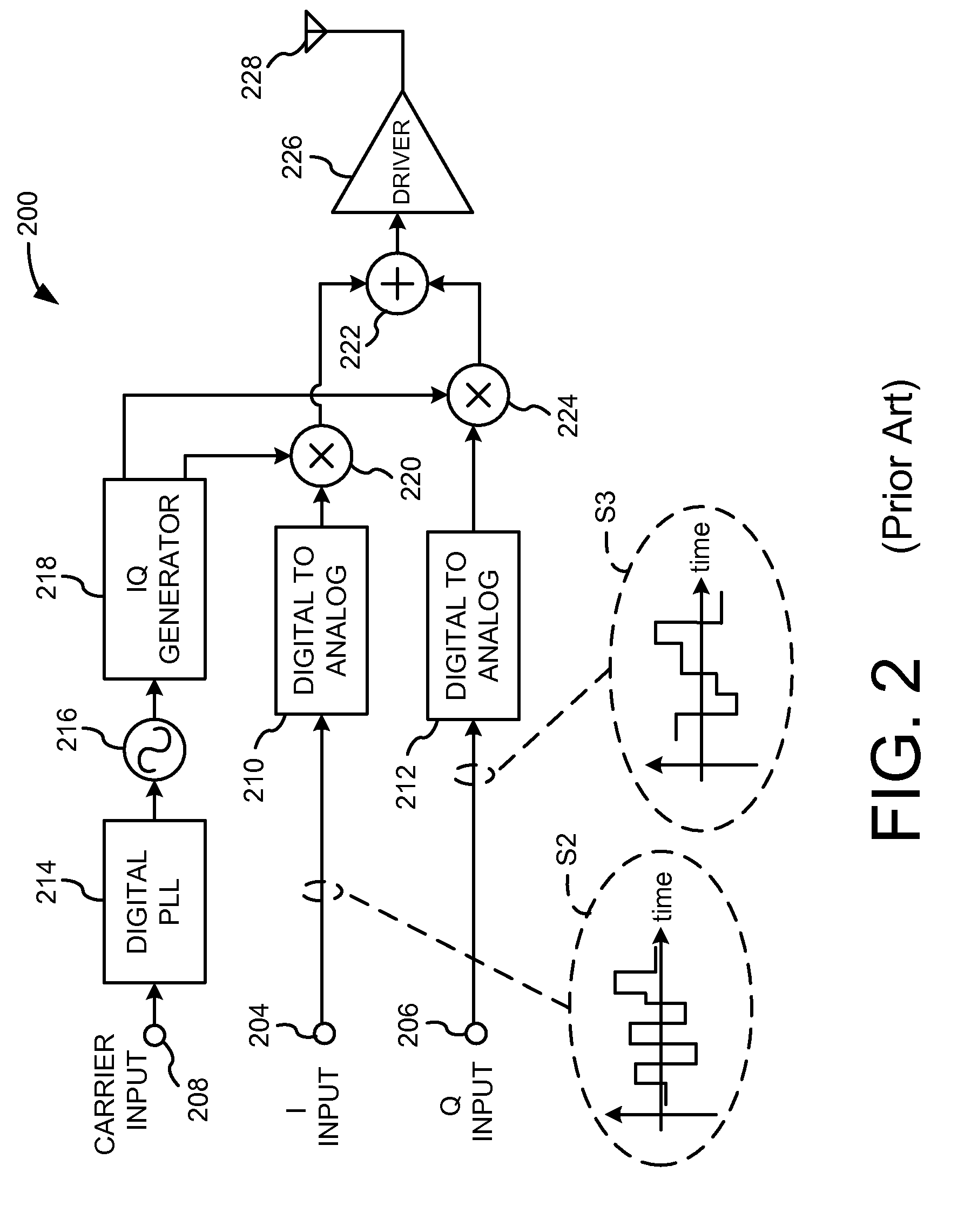
However, disadvantages regarding implementation and efficiency under IQ modulation stem from the fact that the in-phase and quadrature modulation signals span respective value ranges having both positive and negative values (i.e., signal polarities).
Thus, within an IQ modulation context, the DAC stages require sufficient circuit complexity and operating speed to convert bi-polar input signals.
Such requirements can be difficult to achieve, particularly in a mass production environment.
An undesirable consequence of this approach is that the advantages and speed of class-B operation no longer exist.

Method used


Image

  • Highly Optimized Digital IQ Transmitter Chain
  • Highly Optimized Digital IQ Transmitter Chain
  • Highly Optimized Digital IQ Transmitter Chain

Examples


Embodiment Construction

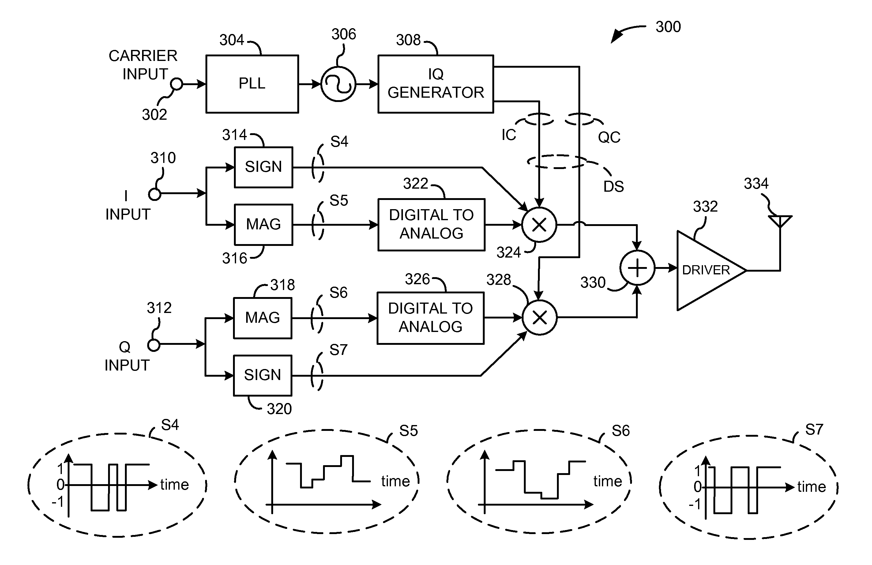
[0022]Disclosed herein are circuits for use with wireless systems. According to one implementation, an electronic circuit separates a digital modulation signal into a digital sign signal and a digital magnitude signal. A digital-to-analog converter converts the digital magnitude signal into an analog magnitude signal. A mixer then mixes at least the analog in-phase magnitude signal and the digital in phase sign signal to provide a mixed signal.

[0023]According to another implementation, an electronic circuit includes elements configured to define a digital-to-analog converter (DAC). The DAC is configured to perform responsive to a multi-state switching signal and an in-phase and quadrature (IQ) differential signal. The circuitry further includes elements cooperatively configured to define a mixer. The mixer receives signals from the DAC, and performs mixing responsive to a digital sign signal. The mixer couples the mixed signal to a pair of output nodes.

[0024]According to still anoth...


PUM


Abstract

Circuitry separates a modulation signal into digital sign and magnitude signal components. The digital magnitude signal is converted to an analog magnitude signal. The analog magnitude signal is the mixed with an in-phase or quadrature carrier signal under the influence of the digital sign signal and routed to a driver output stage.

Description

BACKGROUND[0001]System-on-chip (SoC) integration on CMOS within wireless systems, in conjunction with the ongoing CMOS shrinkage path, requires appreciable redesign in order to accommodate industry goals. This is especially true for radio frequency (RF) and some analog devices. The result of the continuous march toward integration and miniaturization is that architectures require increased digital circuitry and a reduction in purely analog sub-systems.[0002]Multi-modal radios and other wireless devices present their own challenges in regard to the foregoing paradigm. In particular, respective developments for receivers, synthesizers and transmitters are needed to optimize overall system design. Additional goals in this regard include area savings and reduced current and power consumption. In short, improved SoC design is desirable as applied to wireless and other devices.[0003]Illustrative Background Structures[0004]FIG. 1 shows a transmitter structure (transmitter) 100 in accordanc...

Claims


Application Information

Patent Timeline
IPC IPC(8): H04L27/32H03M13/29
CPCH03C3/40H03C5/00H03D2200/0052H03D7/1441H03D7/165H03C1/36
Inventor VAN WAASEN, STEFAN
Owner APPLE INC
Learn More