
Keyhole computed tomography

a computed tomography and keyhole technology, applied in tomography, instruments, applications, etc., can solve the problems of inability to accurately match the estimated projection data with the measured projection data, quantitatively inaccurate regions throughout the reconstructed image, and visible artifacts at the periphery of the reconstructed image, etc., and achieve computationally expensive approaches

Active Publication Date: 2009-09-10
GENERAL ELECTRIC CO
View PDF32 Cites 23 Cited by
  • Summary
  • Abstract
  • Description
  • Claims
  • Application Information

AI Technical Summary

Problems solved by technology

However, if the estimated projection data do not support the signal from outside the targeted FOV, the estimated projection data cannot correctly match the measured projection data.
If the signal from outside the targeted FOV is not accounted for, the entire signal from outside the targeted FOV may be assigned to the periphery of the targeted FOV or may produce aliasing artifacts inside the targeted FOV.
This approach may result in a visible artifact at the periphery of the reconstructed image and quantitatively inaccurate regions throughout the reconstructed image.
As the computational time and image storage requirements grow significantly based on the number of pixels in the reconstruction, this approach may be computationally expensive.

Method used


Image

  • Keyhole computed tomography
  • Keyhole computed tomography
  • Keyhole computed tomography

Examples


Embodiment Construction

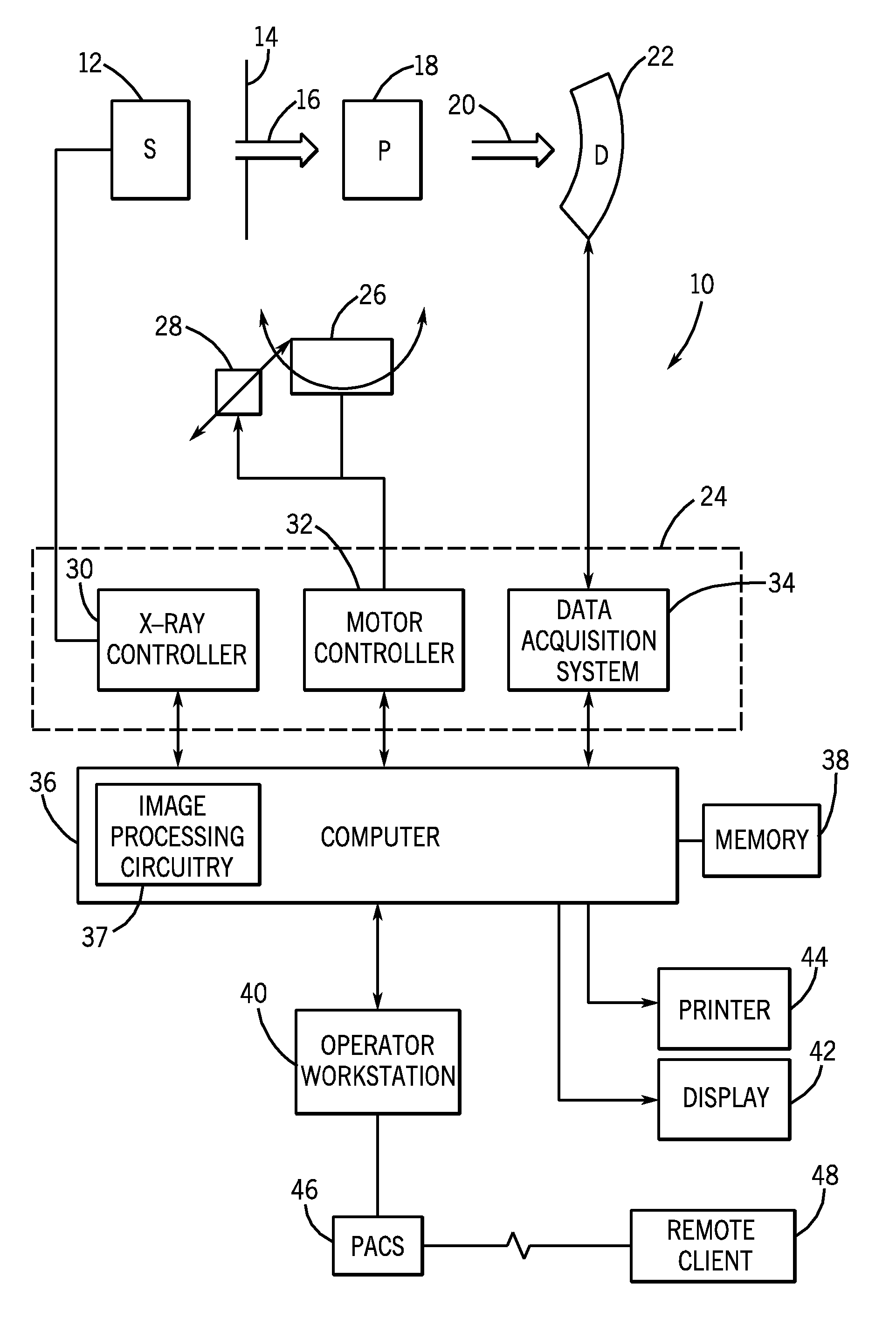
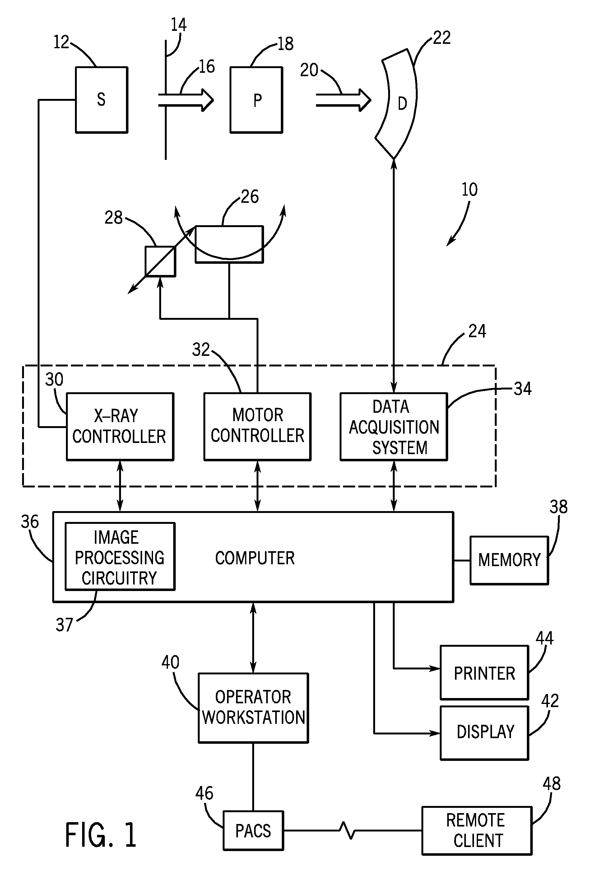
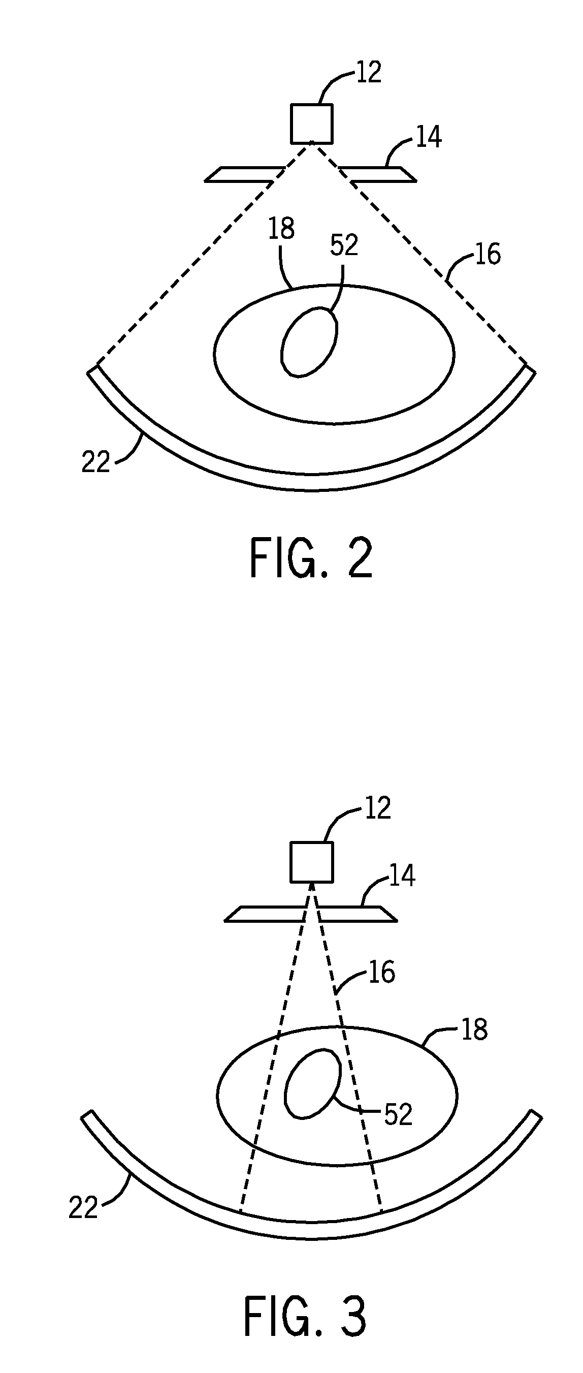
[0024]The embodiments discussed below provide a technique for dynamic CT imaging. More specifically, certain embodiments include acquiring at least one full field of view (FOV) (background) image and a plurality of images of a targeted FOV that is contained with the region associated with the background image. To provide for improved processing performance, in certain embodiments, data in the region of the background image that corresponds to the targeted FOV is replaced with the data from each of the images in the targeted FOV. In some embodiments, one or more of the plurality of images including the targeted FOV are reconstructed based on the data in the targeted FOV and the surrounding data of the background image. Accordingly, in certain embodiments, only a single CT scan of a patient is made to acquire the background image and data for processing and additional CT scans are restricted to the targeted FOV, thereby reducing the dose of X-radiation to the patient while accurately ...


PUM


Abstract

A method of acquiring and reconstructing a computed tomography (CT) image is provided. A first scan of the full field of view (FOV) is acquired. A second scan of a smaller target FOV is then acquired by using a collimator to narrow the X-ray beam width. The CT image is iteratively reconstructed by replacing a key-hole region of the full FOV projection data with the target FOV projection data. An exemplary embodiment comprises imaging a heart (target FOV) within a torso (full FOV) over multiple heart beat cycles. A computer readable medium is further provided, including a program configured to reconstruct a CT image using the key-hole method.

Description

CROSS REFERENCE TO RELATED APPLICATIONS[0001]This application is a continuation-in-part of U.S. patent application Ser. No. 11 / 731,612 entitled “ITERATIVE RECONSTRUCTION OF TOMOGRAPHIC IMAGE DATA METHOD AND SYSTEM”, filed Mar. 30, 2007, which is herein incorporated by reference.BACKGROUND[0002]The invention relates generally to non-invasive imaging. More particularly, the invention relates to methods and systems for targeted iterative reconstruction for use in non-invasive imaging.[0003]In the fields of medical imaging and security screening, non-invasive imaging techniques have gained importance due to benefits that include unobtrusiveness, ease, and speed. In medical and research contexts, these imaging systems are used to image organs or tissues beneath the surface of the skin. A number of non-invasive imaging modalities exist today. A particular modality may be selected based upon the organ or tissue to be imaged, upon the spatial and / or temporal resolution desired, or upon whet...

Claims


Application Information

Patent Timeline
IPC IPC(8): H05G1/60G06K9/00
CPCA61B6/032A61B6/037A61B6/469G06T2211/424G06T11/006G06T2211/412A61B6/488
Inventor HUGG, JAMES WILLIAMMANJESHWAR, RAVINDRA MOHAN
Owner GENERAL ELECTRIC CO
Learn More