Process and Apparatus for the Combustion of a Sulfur-Containing Liquid

Inactive Publication Date: 2009-09-10
MECS
View PDF31 Cites 13 Cited by
  • Summary
  • Abstract
  • Description
  • Claims
  • Application Information

AI Technical Summary

Benefits of technology

[0007]Among the objects of the present invention, therefore, are the provision of an improved process and apparatus for the combustion of a sulfur-containing liquid to produce a combustion gas comprising sulfur dioxide wherein the sulfur-containing liquid is pneumatically atomized with an atomizing gas in a sulfur lance to form an atomized sulfur combustion mixture for discharge into the combustion chamber of a sulfur furnace; the provision of such an improved process and apparatus capable of forming a sulfur combustion mixture having desirable particle or droplet size characteristics that

Problems solved by technology

With these large particle sizes, it is difficult to ensure sufficiently rapid vaporization and combustion of the liquid sulfur particles within the combustion chamber volume.
Moreover, hydraulically-operated sulfur lances sometimes suffer from the emission of insufficiently atomized liquid sulfur (i.e., “drool”) from the nozzle of the lance.
As a result of these deficiencies, unburned sulfur sometimes deposits outside the intended combustion zone within the sulfur furnace, particularly in smaller sulfur furnace installations or during times of turndown when the sulfur pressure is reduced, leading to process inefficiency and increased maintenance requirements.
Although the teachings of Anderson are significant, the disclosed apparatu

Method used


Image

  • Process and Apparatus for the Combustion of a Sulfur-Containing Liquid
  • Process and Apparatus for the Combustion of a Sulfur-Containing Liquid
  • Process and Apparatus for the Combustion of a Sulfur-Containing Liquid

Examples


Example

Example 1

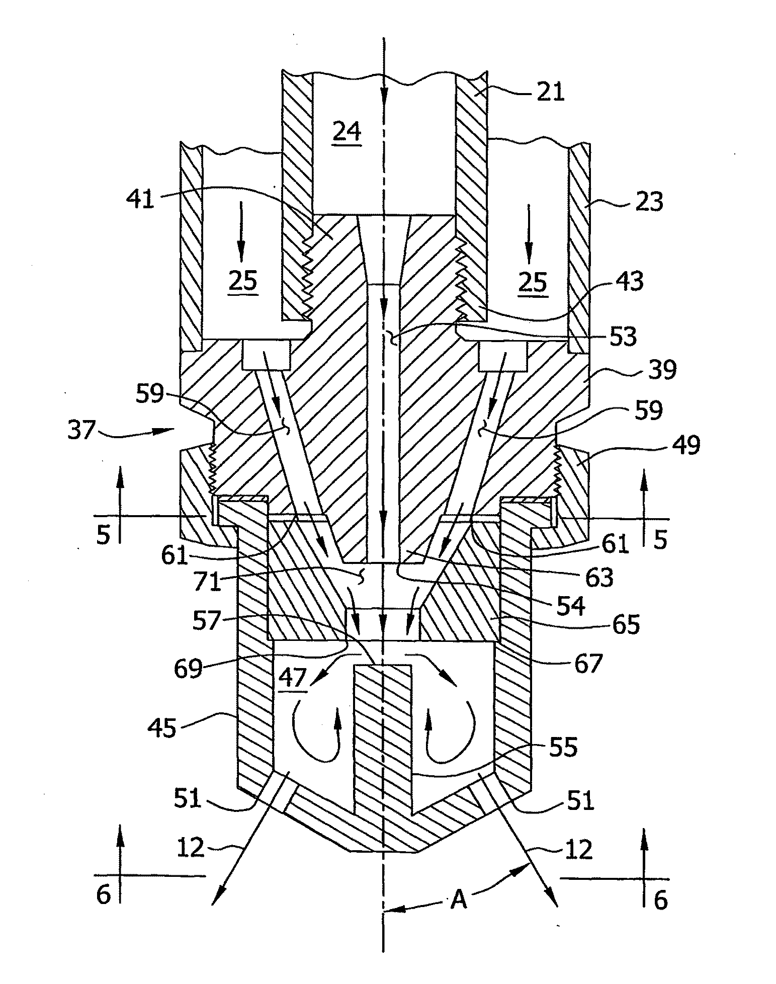
[0056]A pneumatically-operated sulfur lance in accordance with the present invention was tested in a combustion apparatus that burns molten sulfur to generate sulfur dioxide for the production of sulfuric acid. The sulfur lance included a mixing and atomizing spray nozzle of the type described above (FLOMAX, FM25 available from Spraying Systems Company, Wheaton, Ill.) and was supplied with pressurized molten sulfur and undried ambient air as the atomizing gas.

[0057]During the test period, the sulfur lance was operated at two different sulfur flow rates. The sulfur feed rate was initially set at about 12 gpm (45 lpm), then increased to about 23 gpm (87 lpm) after which it was decreased back to about 12 gpm (45 lpm). The duration of the test run lasted 95 minutes.

[0058]The principal tool used for gauging the degree of atomization was visual examination of the sulfur flame. Visual observations were made and digital photographs were taken at each of the test conditions. The con...

Example

Example 2

[0064]A pneumatically-operated sulfur lance in accordance with the present invention was tested to assess nitrogen oxide formation. The pneumatically-operated sulfur lance was installed in a combustion apparatus that burns molten sulfur to generate a combustion gas comprising sulfur dioxide used in the production of sulfuric acid at a contact sulfuric acid production facility. The pneumatically-operated sulfur lance included a mixing and atomizing spray nozzle of the type described above (FLOMAX, FM25 available from Spraying Systems Company, Wheaton, Ill.) and was supplied with pressurized molten sulfur and undried ambient air as the atomizing gas.

[0065]During the test period, the pneumatically-operated sulfur lance was operated at an approximate sulfur flow rate of 35 gpm (132 lpm). As a comparison, two standard hydraulically-operated sulfur lances were also tested in the combustion apparatus of the sulfuric acid plant at an approximate total sulfur flow rate of 35 gpm (13...


PUM


Abstract

Apparatus and processes for the production of a sulfur dioxide-containing combustion gas are provided in which a sulfur-containing liquid is pneumatically atomized with a sulfur gun or lance that utilizes an atomizing gas to form an atomized combustion mixture for combustion in a sulfur furnace. The sulfur dioxide-containing combustion gas may be used in the manufacture of sulfuric acid by the contact process.

Description

FIELD OF THE INVENTION[0001]The present invention relates generally to techniques and apparatus for making an atomized sulfur combustion mixture comprising particles or droplets of a sulfur-containing liquid by atomizing a sulfur-containing liquid utilizing an atomizing gas. The present invention is particularly suited for the production of an atomized sulfur combustion mixture for combustion in a sulfur furnace to produce a sulfur dioxide-containing combustion gas useful in the manufacture of sulfuric acid by the contact process.BACKGROUND OF THE INVENTION[0002]The conventional contact process for the manufacture of sulfuric acid includes burning or combusting molten sulfur in air or other oxygen-containing gas in the combustion chamber of a sulfur furnace to produce a combustion gas comprising sulfur dioxide, oxidizing the sulfur dioxide produced in one or more catalytic oxidation stages of a converter to produce a conversion gas comprising sulfur trioxide, and absorbing the sulfu...

Claims


Application Information

Patent Timeline
IPC IPC(8): C01B17/50B01J10/00
CPCB01J4/002B05B1/265B05B7/0475F23D11/102B05B7/0892C01B17/54B05B7/0483
Inventor RANDOLPH, III, DAVIDCHAN, SAMUEL
Owner MECS
Why Eureka
Try Eureka