
Solar Cell

a solar cell and cell technology, applied in the field of solar cells, can solve the problems of increasing the cost of maintenance, affecting the precision of the dimensions of the first pattern, and the occurrence of dust and water in the concave pattern, so as to prevent the accumulation of dust and water more effectively, and the precision of the first pattern's dimensions is more easily controlled

Inactive Publication Date: 2009-09-17
FLYPOWER INT
View PDF4 Cites 22 Cited by
  • Summary
  • Abstract
  • Description
  • Claims
  • Application Information

AI Technical Summary

Benefits of technology

[0008]The present invention provides a solar cell, wherein the incident surface of a transparent cover plate thereof can present the accumulation of dust and / or water more effectively, and patterns on the incident surface can be more precisely formed.
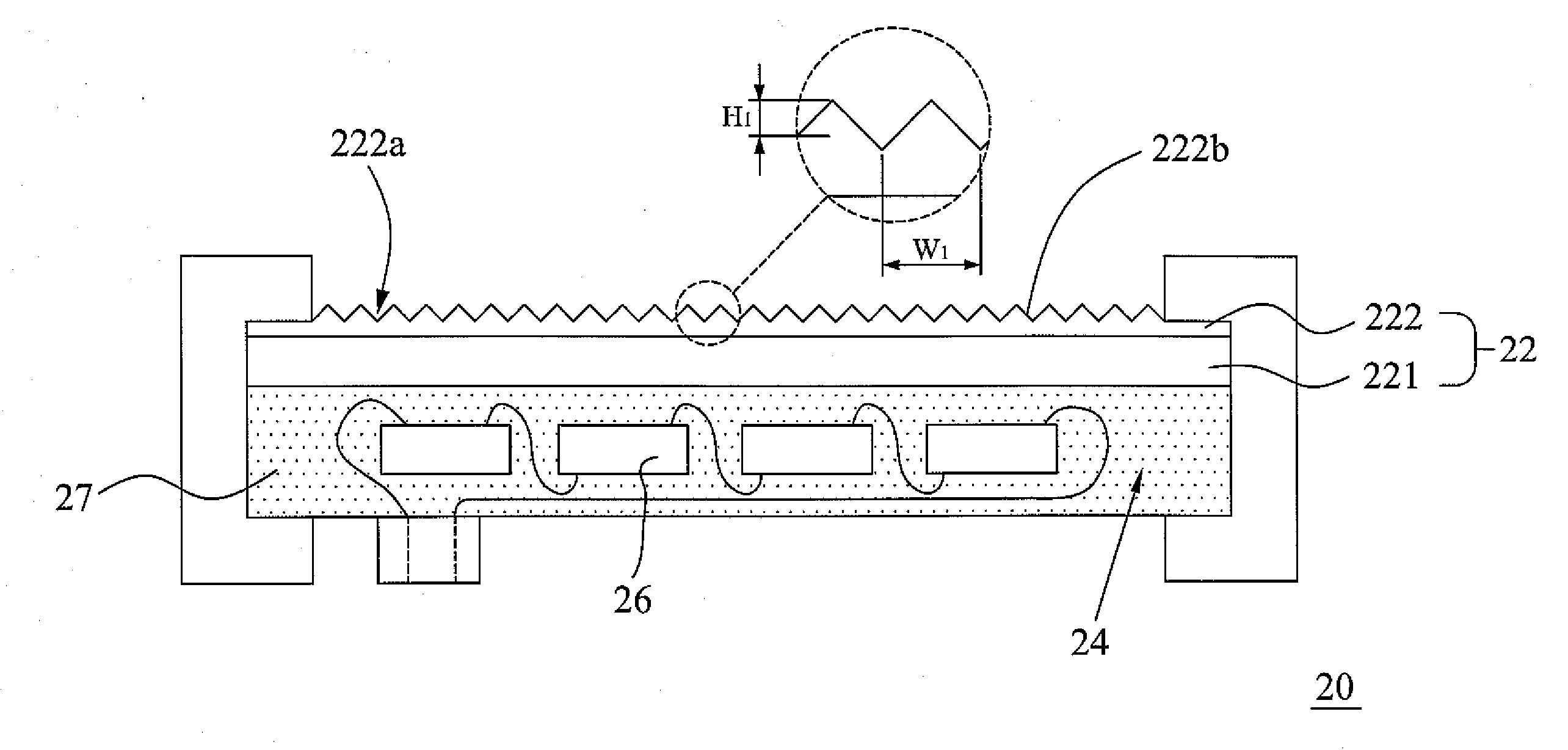
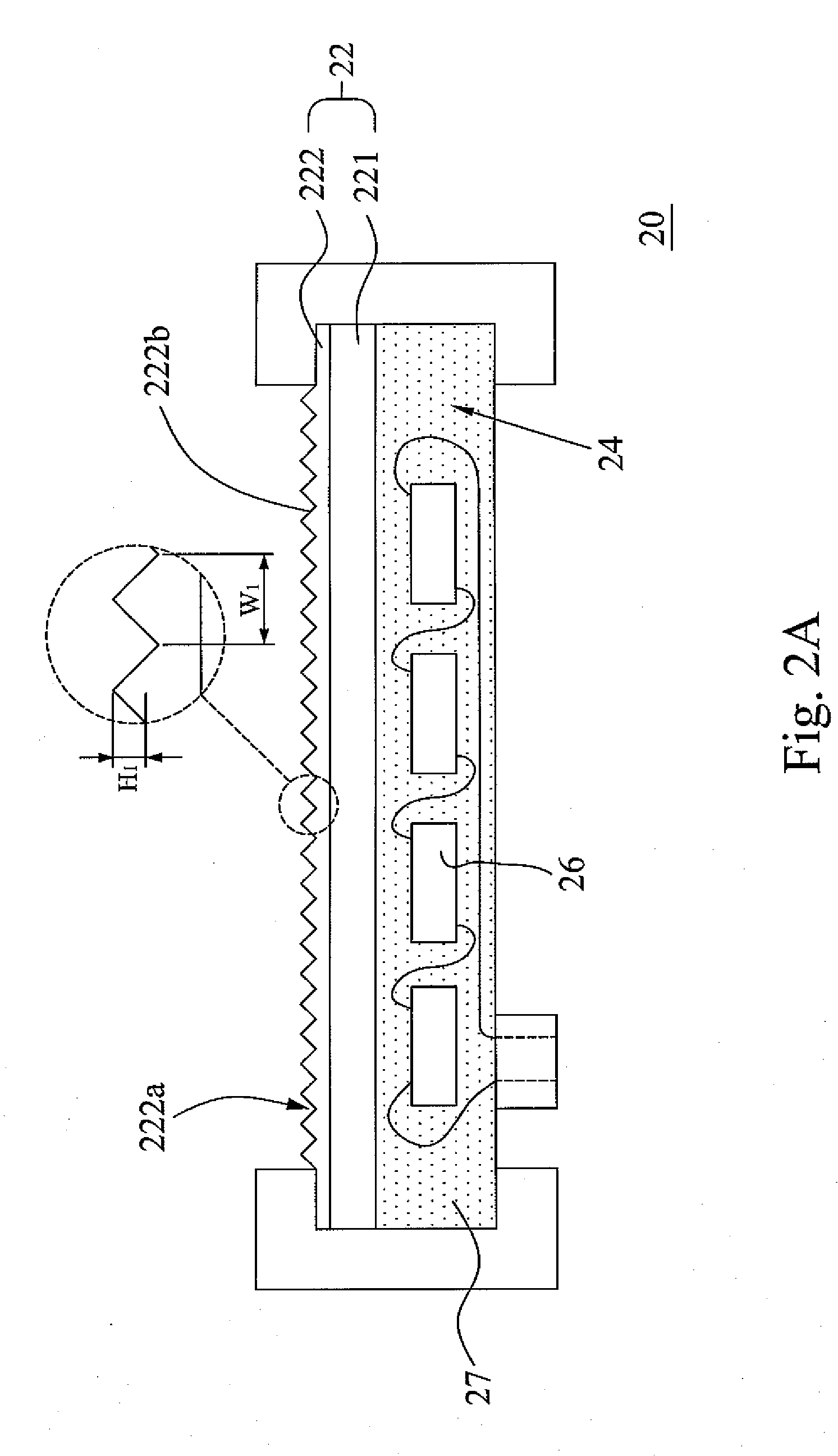
[0015]Due to the convex first patterns disposed on the transparent cover plate, the transparent cover plate can prevent the accumulation of dust and water more effectively. Moreover, the structured plate is made from a photo resin, which shrinks slightly during curing. Therefore, the precision of the dimensions of the first patterns is more easily controlled and the transparent cover plate can reach the requirement for the optic effect as well.

Problems solved by technology

However, the concave patterns are apt to accumulate dust and / or water, especially in the desert.
Therefore, the glass cover plate needs cleaning frequently, increasing the cost of maintenance.
As the glass cools down, the patterns thereof shrink due to the larger expansion coefficient of glass, with the result that the dimensions of patterns are often undesirable.

Method used


Image

  • Solar Cell
  • Solar Cell
  • Solar Cell

Examples


first embodiment

[0026]Please refer to FIG. 2A for a solar cell of a The solar cell 20 defines a receiving room 24, which includes an encapsulant material 27 and pluralities of cell units 26. The encapsulant material 27 is ethylene-vinyl acetate copolymer for example and the cell units 26 are singlesilicon solar cells in the present embodiment. However, the cell units 26 can be dye sensitized solar cells, polysilicon solar cells or other apparatus which can transform light energy into electric energy. Moreover, a transparent cover plate 22 is placed over the cell units 26. The transparent cover plate 22 includes a base plate 221 and a structured plate 222. The base plate 221 is made from glass, wherein the thickness thereof is between 3 mm to 12 mm. The structured plate 222 is made from a photo resin, such as a UV-curable resin. However, those skilled in the art can also select other inflexible material as the material of the base plate 221, such as polymethyl methacrylate (PMMA), polycarbonate (PC...

third embodiment

[0034]Moreover, those skilled in the art can also vary the first patterns into structures other than bar-shaped structure. Please refer to FIG. 6 for a top view of a transparent cover plate of a solar cell of the The bases of the first patterns 222b″ on the transparent cover plate 222 are circular.

[0035]Then, please refer to FIG. 7 for a transparent cover plate of the solar cell of the fourth embodiment. The difference between the present transparent cover plate 22′″ and the transparent cover plate 22″ of the second embodiment is that there is a transparent waterproof material 223′″ applied on the structured plate 222′ of the transparent cover plate 22′″. The waterproof material 223′″ is polytetrafluoro ethylene, for example. In the present embodiment, it is not easy for water to adhere on the transparent cover plate 22′″ due to the waterproof material 223′″.


PUM


Abstract

A solar cell is provided. The solar cell defines a receiving room in where at least a cell unit is located. A transparent cover plate is placed over the cell unit. In addition, the transparent cover plate includes a base plate and a structured plate which are adhered to each other. Wherein, the base plate is made from inflexible material and the structured plate is made from a photo resin. Moreover, there are pluralities of convex first patterns disposed on the incident surface of the structured plate.

Description

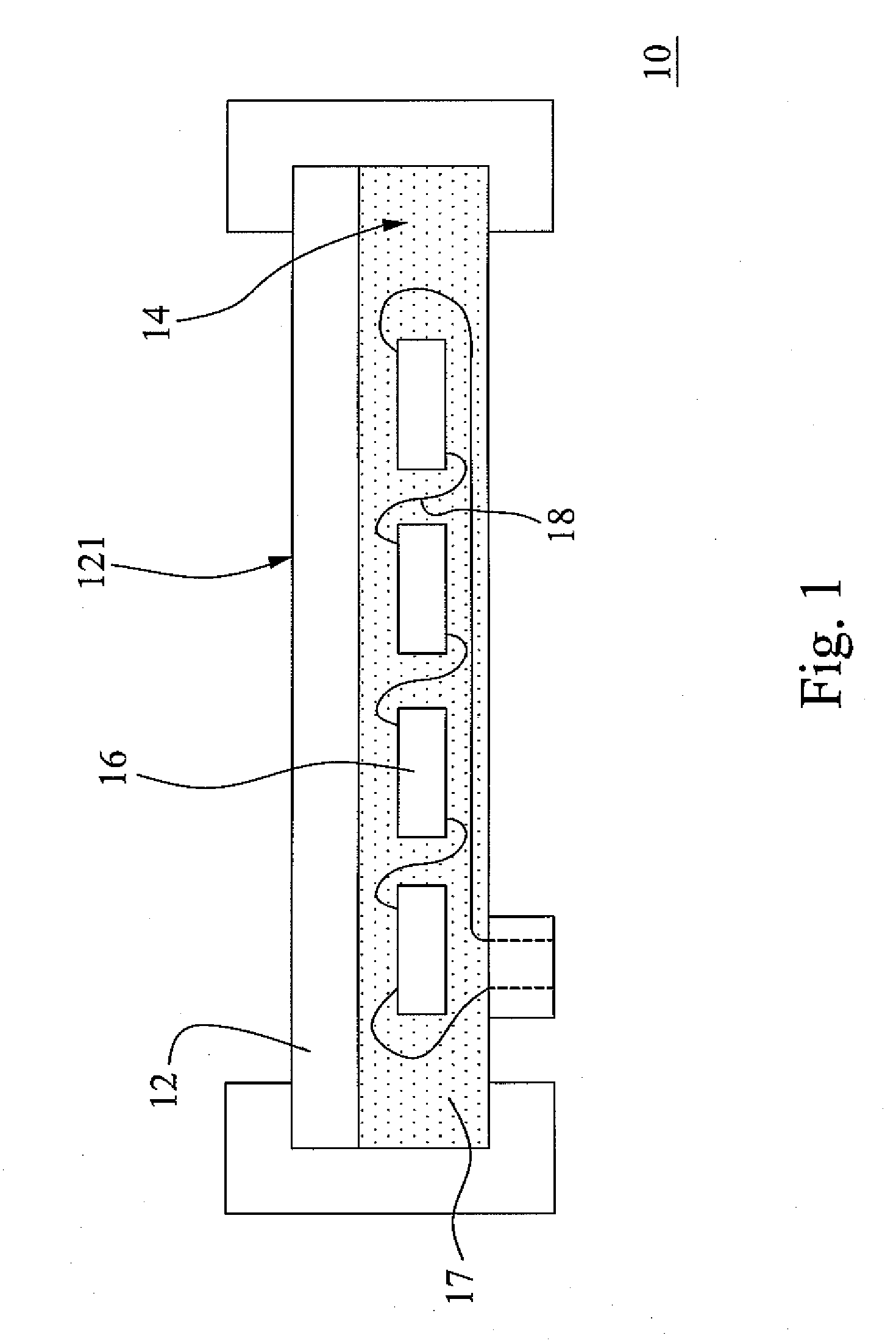
BACKGROUND OF THE INVENTION[0001]1. Field of the Invention[0002]The present invention relates to a solar cell. More particularly, the present invention relates to a solar cell with a transparent cover plate which includes a base plate and a structured plate.[0003]2. Description of the Prior Art[0004]In the recent years, the greenhouse effect caused by the mass generation of greenhouse gas and the price upswing of petroleum result in the fact that people are giving more and more weight to the renewable energy. In the present, the renewable energy includes: solar energy, wind power, geothermal energy, hydro power, tide energy, ocean thermal energy conversion and biomass energy, wherein the solar energy is the most generally used among the renewable energy.[0005]Please refer to FIG. 1 for a prior solar cell. The solar cell 10 defines a receiving room 14, which includes an encapsulant material 17 and pluralities of polysilicon solar cells 16. The polysilicon solar cells 16 are connected...

Claims


Application Information

Patent Timeline
IPC IPC(8): H01L31/048
CPCH01L31/0236Y02E10/50H01L31/048H02S40/10H02S40/20
Inventor LEE, CHEN-SHENG
Owner FLYPOWER INT
Learn More