Hydro-wind power generating turbine system and retrofitting method

Inactive Publication Date: 2009-09-17
PERRY ROBERT NELSON
View PDF8 Cites 56 Cited by
  • Summary
  • Abstract
  • Description
  • Claims
  • Application Information

AI Technical Summary

Benefits of technology

[0007]In one aspect, the present invention electrically isolates the hydraulic pump and the wind turbine shaft from the metal support tower. The electrical isolation can be accomplished in several ways. The upper part of the present metal support tower can have the upper end supplemented by a dielectric material such as fiberglass, polymer ceramic, or commercially available porcelain insulators. A cast material (such as the polymer ceramic) can be utilized to act as both an isolating dielectric material and formed to provide a support platform for the pump and turbine shaft as well as a weather enclosure for the pump. This material can be used instead of metal, in part, due to the lighter weight support requirements of the design of the present invention.
[0008]Using hydraulics as an intermediary between the wind turbine shaft and the generator has several advantages. An unloading valve can be placed between the pressure and return hydraulic lines at ground level, to allow the turbine bl

Problems solved by technology

The limitation is the torque required

Method used


Image

  • Hydro-wind power generating turbine system and retrofitting method
  • Hydro-wind power generating turbine system and retrofitting method
  • Hydro-wind power generating turbine system and retrofitting method

Examples


Embodiment Construction

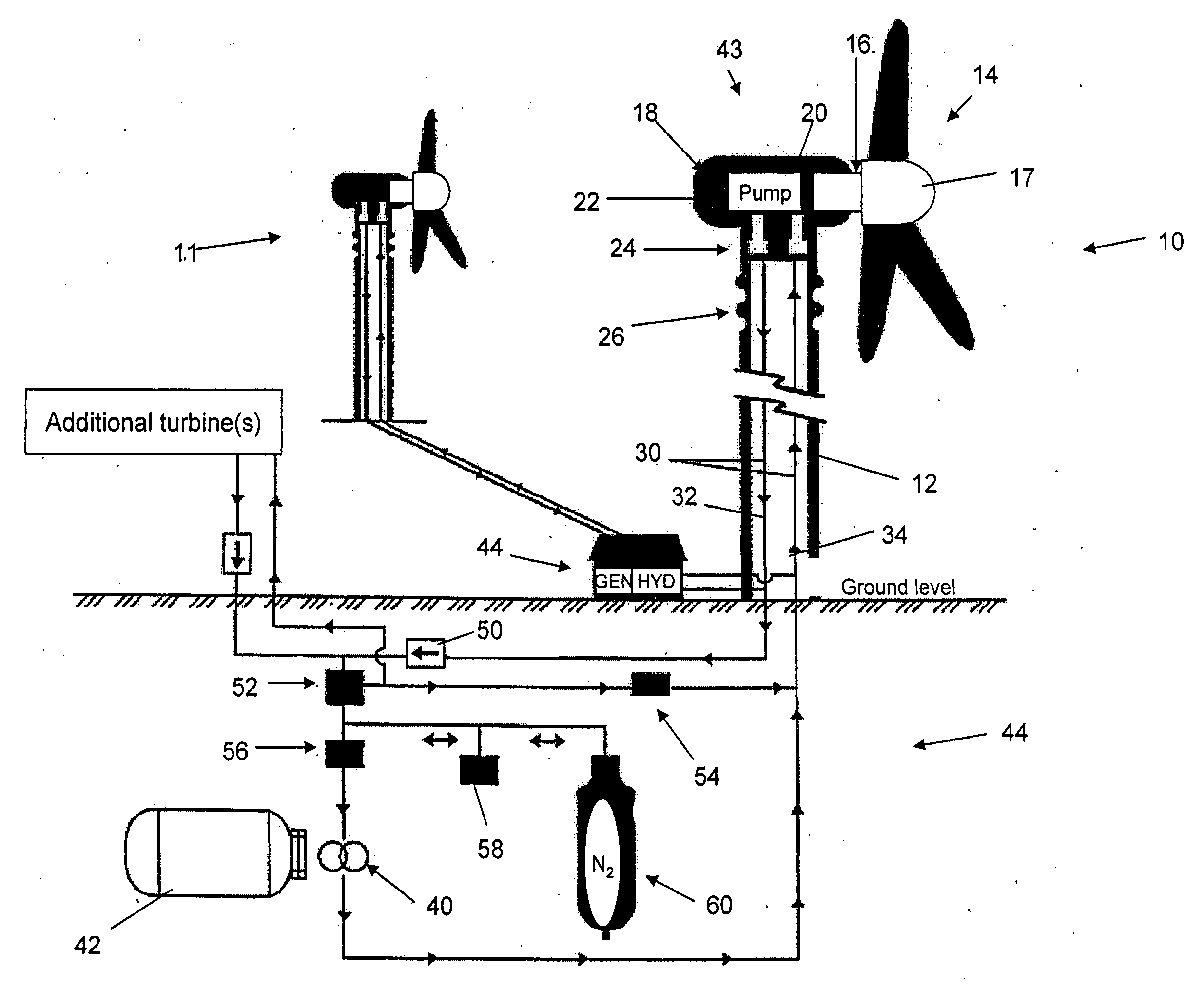
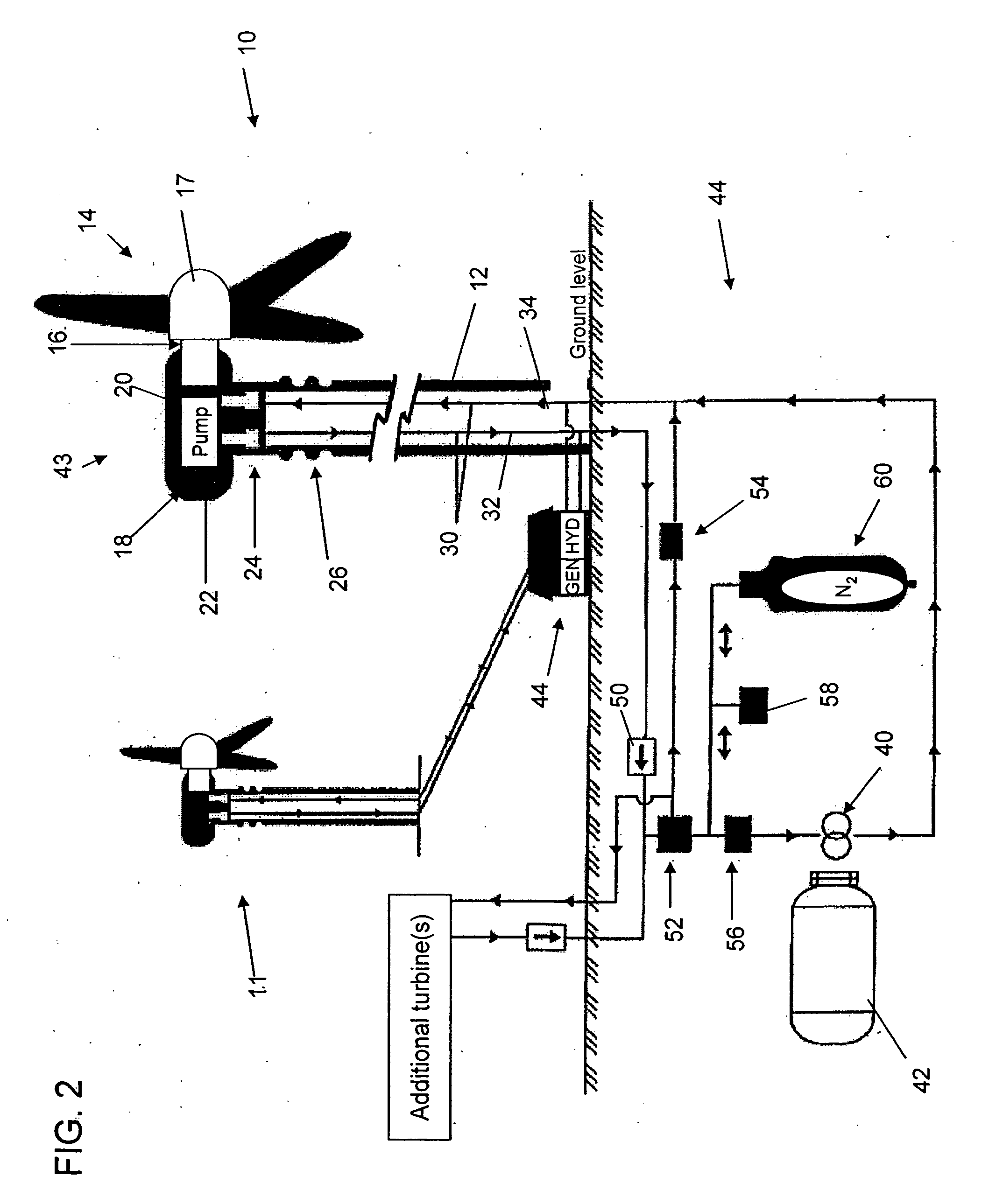
[0017]As shown in FIG. 2, there is provided a wind turbine system 10 in accordance with one embodiment of the present invention. The system includes a tower 12 having a blade and / or propeller arrangement 14 including at least two and typically three blades mounted on a blade shaft 16 with a hub member 17, wherein the blade shaft is mechanically coupled to a hydraulic pump 20 maintained within nacelle 18. Hydraulic pump forms part of the hydraulic transmission system of the present invention. Hydraulic transmission system includes an above-ground transmission component 43 and a ground level transmission component44, with above-ground transmission component including the pump 20 and reservoir 22 with an appropriate suction line between the two as is known in the art.

[0018]The pump 20 is a variable displacement pump, such as a radial piston pump, wobble plate pump, swash plate pump or a bent axis pump, for example, and the pump works in a rotary fashion, whereby it develops a partial v...


PUM


Abstract

An electrical power producing wind turbine eliminates the possibility of being struck by lightning, reduces the complexity of gear trains and simplifies maintenance at heights. The wind turbine is electrically isolated from ground to reduce the possibility of being struck by lightning and the generator is located at ground level to simplify maintenance. The turbine blade shaft is directly attached to a hydraulic pump. The hydraulic fluid is transmitted to ground level through dielectric tubing and acts both as an electrical isolating medium and a transmitter of mechanical energy to the generator located at ground level. The wind turbine blade, shaft and hydraulic pump are electrically isolated from the support structure at the upper end.

Description

FIELD OF THE INVENTION[0001]The present invention relates to wind turbines, and more particularly to a wind turbine having a hydraulic transmission and an associated method for retrofitting standard wind turbine systems.BACKGROUND OF THE INVENTION[0002]Electrical power producing wind turbines are a supplement to power generating stations using fossil fuels or nuclear fuel to produce electricity. The primary components of current wind turbines are blades, blade shafts, a gear train and a generator. The gear train increases the speed of rotation of the shaft to run the generator at higher speeds of rotation than the turbine blades are rotating. The gear train and the generator combine to weigh more than twenty tons in many modern wind turbine implementations. A sample gear train is shown at 60 in FIG. 1, with the blade shaft 61 being coupled with a larger gear 62, which can then interact with appropriately sized intermediate gears 63 and a generator shaft gear 64 to drive the generato...

Claims


Application Information

Patent Timeline
IPC IPC(8): F03D9/00
CPCF03D11/02Y02E10/722F05B2260/406F03D15/00F03D15/20F03D9/28F03D9/25F03D9/17F03D13/20Y02E10/72Y02E60/16Y02P80/10Y02E70/30
Inventor TORRES, ROSALIAPERRY, E. ROBERT
Owner PERRY ROBERT NELSON
Why Eureka
Try Eureka