Assembly of light-emitting units

a technology of light-emitting units and components, which is applied in the direction of discharge tube luminescnet screens, semiconductor devices for light sources, lighting and heating apparatus, etc., can solve the problems of inconvenient use of light-emitting diodes, insignificant shade may often be ignored by users, and no mature commercialization, etc., to achieve excellent light transmittance, enhance overall brightness, and eliminate dazzling effects

Inactive Publication Date: 2009-09-17
KAO HSUEH CHUNG +1
View PDF10 Cites 21 Cited by
  • Summary
  • Abstract
  • Description
  • Claims
  • Application Information

AI Technical Summary

Benefits of technology

[0005]To realize the objective of overcoming the drawbacks of the conventional devices, an assembly of lighting units is provided in accordance with the present invention, which is applicable to a lighting device, which features enhancement of the overall brightness and elimination of dazzling by providing a light-transmitting hood below the lighting elements.
[0006]The present invention relates to an assembly of light units, which is applicable to a lighting device comprising a plurality of light-emitting elements that are mounted respectively to heat dissipation units. The light-emitting elements project light beams outward through a light-transmitting hood, wherein the light-transmitting hood is made of a material having excellent light transmittance and has a surface on which a light diffusion layer featuring light refraction is provided. As such, with a plurality of point light sources giving off light beams that are converted into light that is in the form of a surface light source for projecting outward, the phenomena of overlap of multiple shades is overcome and light energy of the lighting device can be properly concentrated to enhance the brightness. The lighting device can be applied to various lighting facility and has the advantage of being practical.

Problems solved by technology

With the light emission surface of the light source being strongly homogenized, when the light source is shaped as a sphere, a bar, or a U-shaped rod, the homogenized outward-projecting light does not easily causes a significant shadow of an irradiated object, and such a insignificant shade may often be ignored by a user, if the user does not pay particular attention to it.
However, due to the current trend of environmental protection and conservation of power, the above discussed lighting elements are to be replaced and banned for future use.
This makes the use of the light-emitting diode inconvenient and shows no mature commercialization.
Further, a single light-emitting diode does not provide an illumination that is as high as the conventional lighting units, so that it often need to combine multiple light-emitting diodes together as a single lighting device by which total illumination can be enhanced with the large number of light-emitting diodes used together and the minimum requirement of lighting regulation can be met.
In an arrangement of combining a plurality of lighting elements having substantially the same lighting power, since the locations of adjacent lighting elements are extremely close and the elements have substantially the same brightness, a phenomena of “shade overlap” often occurs, which may easily interfere with the user's eyesight, deteriorating the concentration of the user and causing fatigue of eyes.

Method used


Image

  • Assembly of light-emitting units
  • Assembly of light-emitting units
  • Assembly of light-emitting units

Examples


Embodiment Construction

[0019]The following descriptions are exemplary embodiments only, and are not intended to limit the scope, applicability or configuration of the invention in any way. Rather, the following description provides a convenient illustration for implementing exemplary embodiments of the invention. Various changes to the described embodiments may be made in the function and arrangement of the elements described without departing from the scope of the invention as set forth in the appended claims.

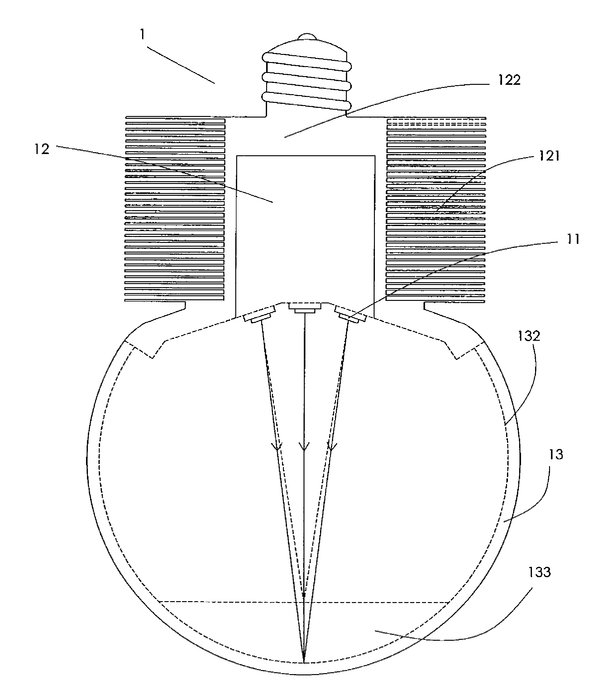
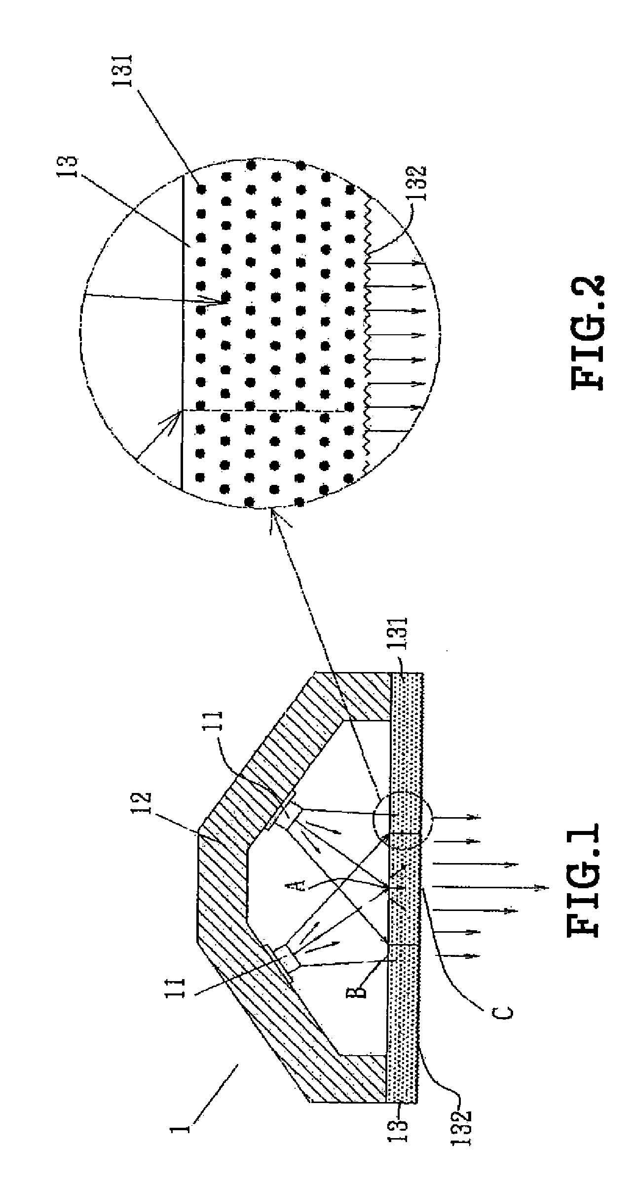
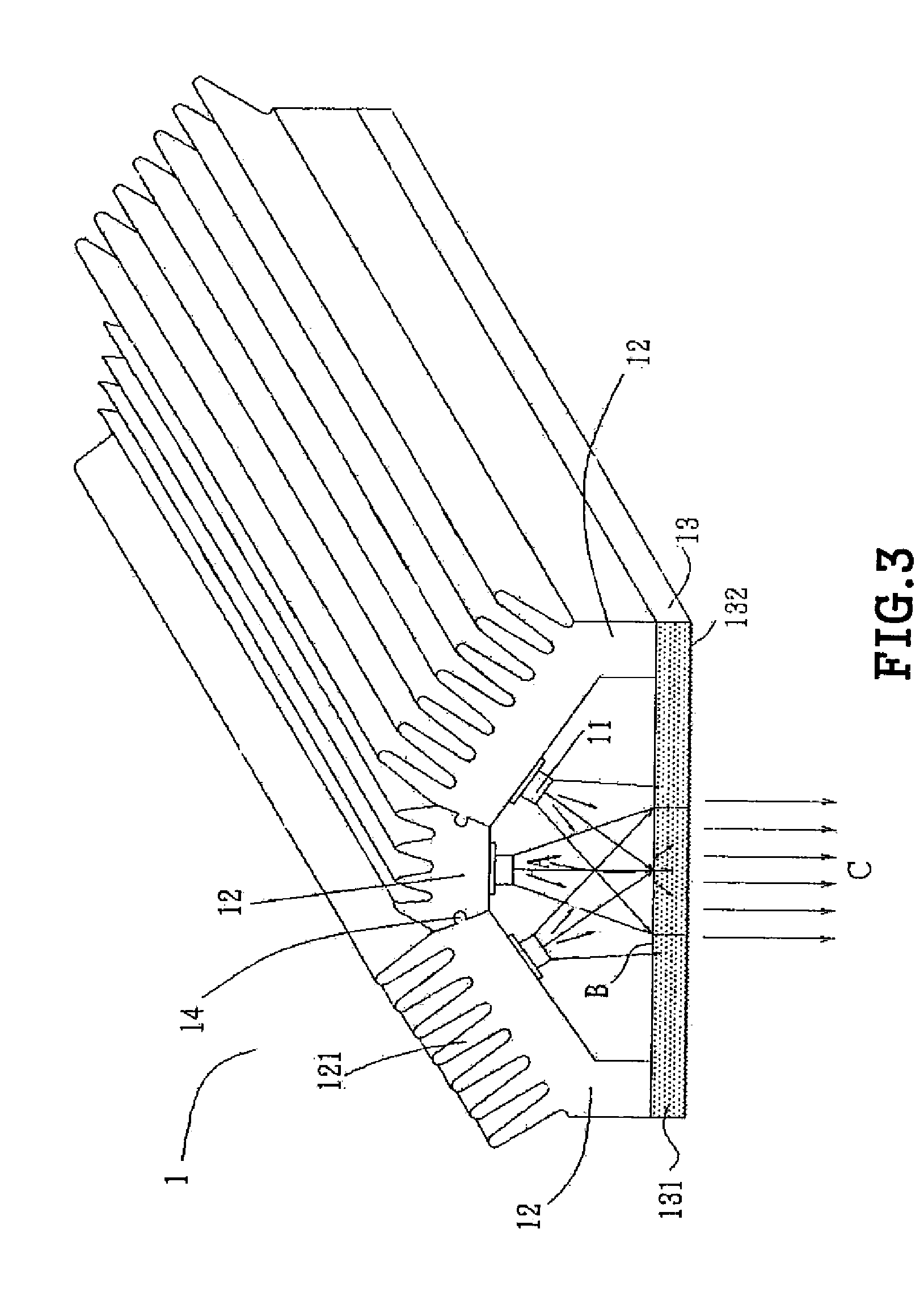
[0020]With reference to the drawings and in particular to FIG. 1, which shows a schematic cross-sectional view of the present invention, a lighting device 1 comprises a plurality of light-emitting elements 11, a heat dissipation unit 12, and a light-transmitting hood 13.

[0021]The plurality of light-emitting elements 11 is arranged at different angles inside the lighting device 1 and may project light beams that converge at an incidence focusing spot A and jointly covers a light incidence area B.

[002...


PUM


Abstract

Disclosed is an assembly of light-emitting units, which is applicable to a lighting device that comprises a plurality of light-emitting elements respectively mounted to heat dissipation units. The light-emitting elements give off light beams that project outward through a light-transmitting hood. One surface of the light-transmitting hood is provided with a light diffusion layer featuring light refraction. As such, the light beams emitting from the light-emitting elements are made converging on a light incidence area, which, together with the feature of light spreading of the light-transmitting hood, can spread off and thus homogenize the light beams to form a surface source, and can also concentrate the light energy of the lighting device to enhance the brightness. The lighting device can be applied to any lighting facility.

Description

TECHNICAL FIELD OF THE INVENTION[0001]The present invention generally relates to an assembly of light-emitting units, and particularly to a light-emitting structure applicable to any lighting unit or facility, in such a way that light beams from a plurality of light-emitting elements converging at a light incidence area, together with the features of diffusion and homogenization of light of a light-transmitting hood, makes it possible to realize concentration of light sources to enhance the brightness of the lighting device and also to effectively homogenize lighting provided by multiple light beams, as well as effective in suppressing the generation of overlap of multiple shades.DESCRIPTION OF THE PRIOR ART[0002]Lighting and illuminating units that are commonly used in daily living includes the traditional tungsten filament based incandescent lamp bulbs, elongate bar like mercury-containing fluorescent tubes, and spiral or multiple-U-shaped power-saving bulbs. These known lighting ...

Claims


Application Information

Patent Timeline
Patent Type & Authority Applications(United States)
IPC IPC(8): H01J61/94
CPCF21Y2101/02F21V3/00F21K9/135F21Y2111/002F21V29/767F21V29/507F21V29/70F21V29/76F21Y2111/007F21K9/232F21Y2107/10F21Y2107/40F21Y2115/10
Inventor KAO, HSUEH-CHUNGWANG, CHAO-JEN
Owner KAO HSUEH CHUNG
Why Eureka
Try Eureka