Electronic ballast for high intensity discharge lamps

a technology of high intensity discharge and electronic ballast, which is applied in the direction of electric variable regulation, process and machine control, instruments, etc., can solve the problems of sputtering and heating of electrodes, difficult to incorporate in the design of magnetic ballast, and too complex or lack of completeness

Inactive Publication Date: 2009-09-17
ENERGY CONSERVATION TECH
View PDF13 Cites 33 Cited by
  • Summary
  • Abstract
  • Description
  • Claims
  • Application Information

AI Technical Summary

Benefits of technology

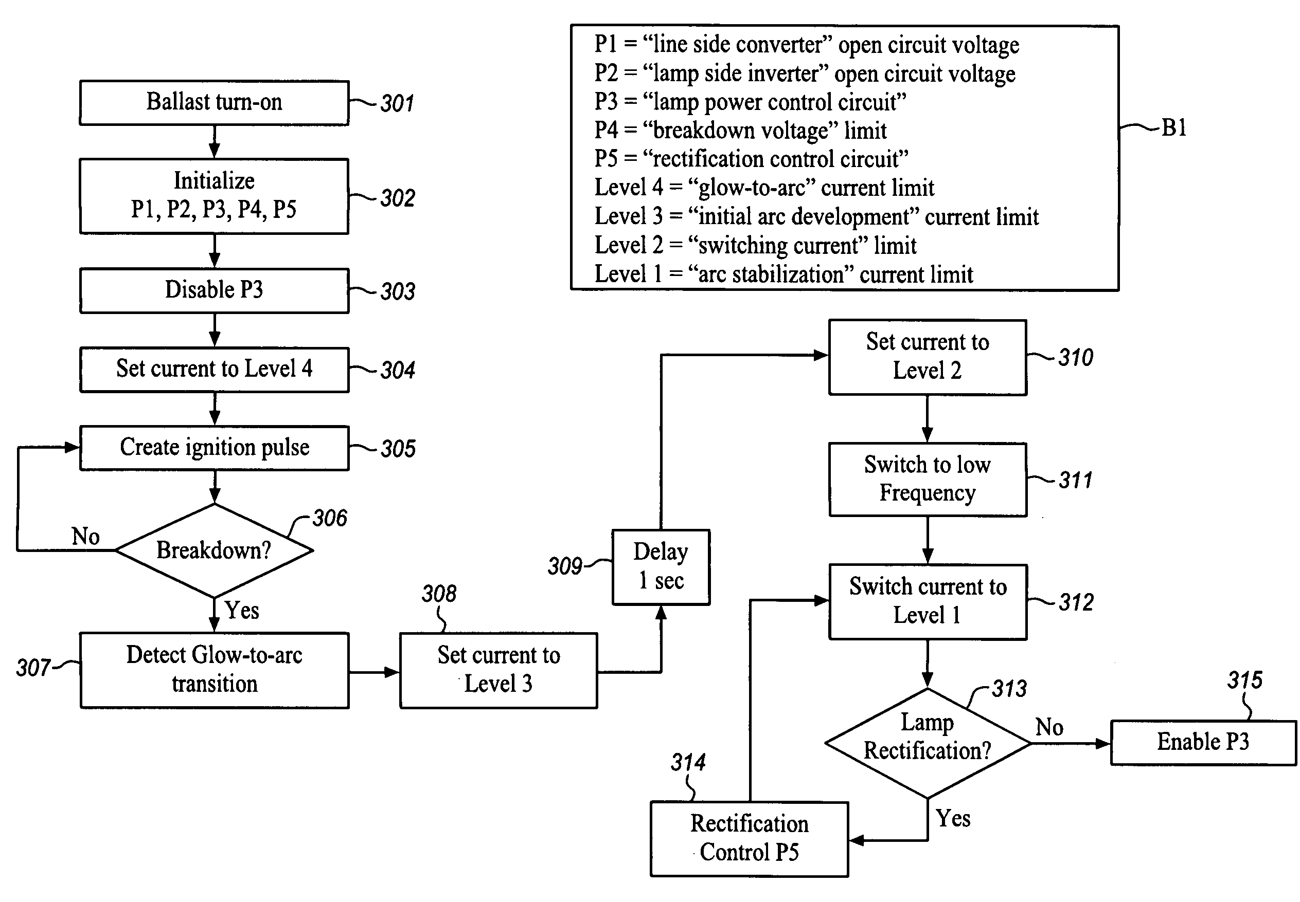
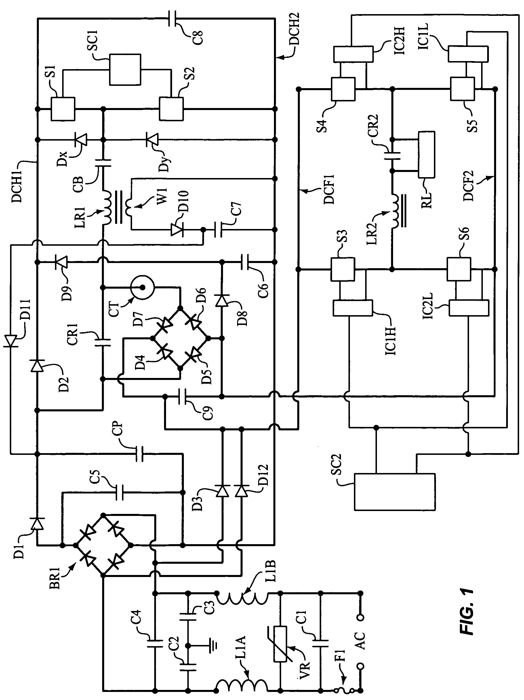
[0011]The present HID electronic lamp ballast uses a “set of controls” that can be performed by controlling energy delivery by the “line side converter” to the “lamp side inverter”. This set of controls comprises: 1) open circuit voltage control, 2) breakdown voltage amplitude control, 3) glow-to-arc transition current control, 4) “initial arc development” current control, 5) “arc stabilization” current control, 6) lamp power control, 7) lamp dimming, 8) “lamp rectification” current control, and 9) short circuit and lamp fault protections. One of the primary advantages of this “line side converter” energy delivery control method is that it doesn't need to vary the lamp operating frequency to achieve the above-noted controls.

Problems solved by technology

Various schemes were proposed in the past to achieve these characteristics, but they are either too complex or lack completeness.
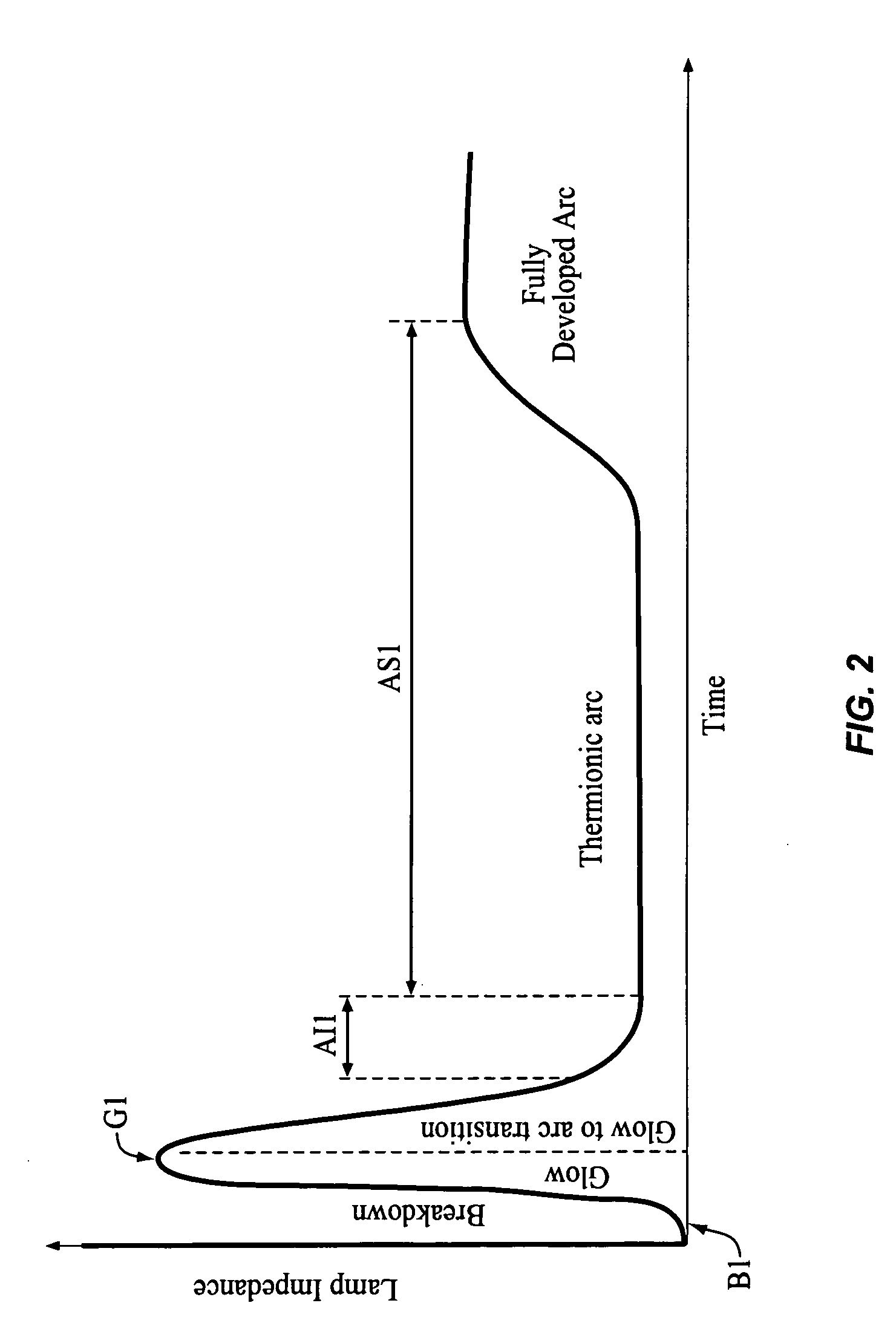
Upon application of a high voltage across an HID lamp, the induced electric field generates seed electrons which cause a breakdown.
The primary source of electrons during this period is secondary emission from the lamp electrodes by ion bombardment, which causes both sputtering and heating of the electrodes.
In order to minimize electrode sputtering during the glow and initial arc phase, balanced and controlled transitions are required, which are difficult to incorporate in the design of magnetic ballast.
Therefore, low frequency electronic ballasts that utilize magnetic ballast ignition schemes provide certain improvements but not all that are desired.
However, none of the electronic ballasts provide a complete electronic ballast architecture that ensures proper lamp ignition and operation, since they typically address a limited number of aspects of lamp ignition and operation.

Method used


Image

  • Electronic ballast for high intensity discharge lamps
  • Electronic ballast for high intensity discharge lamps
  • Electronic ballast for high intensity discharge lamps

Examples


Embodiment Construction

[0032]High Intensity Discharge (HID) lamps are primarily used for large area illuminations. Unlike an incandescent bulb, a ballast device is necessary to ignite and operate an HID lamp. There are three primary functions of a ballast device, namely: 1) lamp ignition, 2) lamp power control, and 3) control of AC line transients and power quality. HID lamps have negative resistance characteristics. Because of these physical characteristics, all gas discharge lamps are current controlled. However, even by maintaining a constant current in the lamp, lamp power cannot be controlled over the life of the lamp because the lamp voltage typically increases over the life of the lamp. Therefore, complex electronic ballast circuits are required for the proper ignition, control, and operation of HID lamps.

Basic Architecture of Electronic Ballast

[0033]FIG. 7 illustrates, in block diagram form, the typical architecture of electronic ballast, which is powered by AC source, while FIG. 8 illustrates, in...


PUM


Abstract

The present High Intensity Discharge electronic lamp ballast uses a “set of controls” that can be performed by controlling energy delivery by the “line side converter” to the “lamp side inverter”. This set of controls comprises: 1) open circuit voltage control, 2) breakdown voltage amplitude control, 3) glow-to-arc transition current control, 4) “initial arc development” current control, 5) “arc stabilization” current control, 6) lamp power control, 7) lamp dimming, 8) “lamp rectification” current control, and 9) short circuit and lamp fault protections. One of the primary advantages of this “line side converter” energy delivery control method is that it doesn't need to vary the lamp operating frequency to achieve the above-noted controls.

Description

FIELD OF THE INVENTION[0001]This application discloses an electronic ballast device for High Intensity Discharge (HID) lamps which implements precise control of lamp ignition, lamp glow-to-arc currents, and operation of High Intensity Discharge lamps.BACKGROUND OF THE INVENTION[0002]High Intensity Discharge (HID) lamps are primarily used for large area illuminations. Unlike an incandescent bulb, a ballast device is necessary to ignite and operate an HID lamp. There are three primary functions of a ballast device, namely: 1) lamp ignition, 2) lamp power control, and 3) control of AC line transients and power quality. Most commonly used HID lamps are high-pressure sodium, ceramic, and pulse start metal halide lamps. All of these lamps require very high voltage for their ignition. Recently, electronic ballasts have been introduced to replace the old magnetic ballasts for higher operating efficiency and to improve lamp life and lumen maintenance by incorporating controlled ignition and ...

Claims


Application Information

Patent Timeline
Patent Type & Authority Applications(United States)
IPC IPC(8): H05B41/36
CPCH05B41/042H05B41/2883Y02B20/208H05B41/388H05B41/2925Y02B20/00
Inventor QUAZI, FAZLE S.
Owner ENERGY CONSERVATION TECH
Why Eureka
Try Eureka