

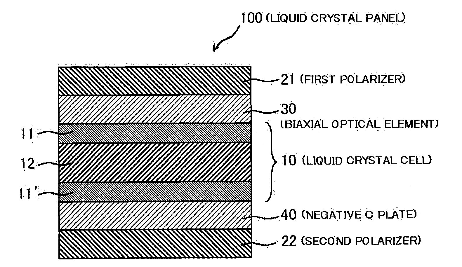
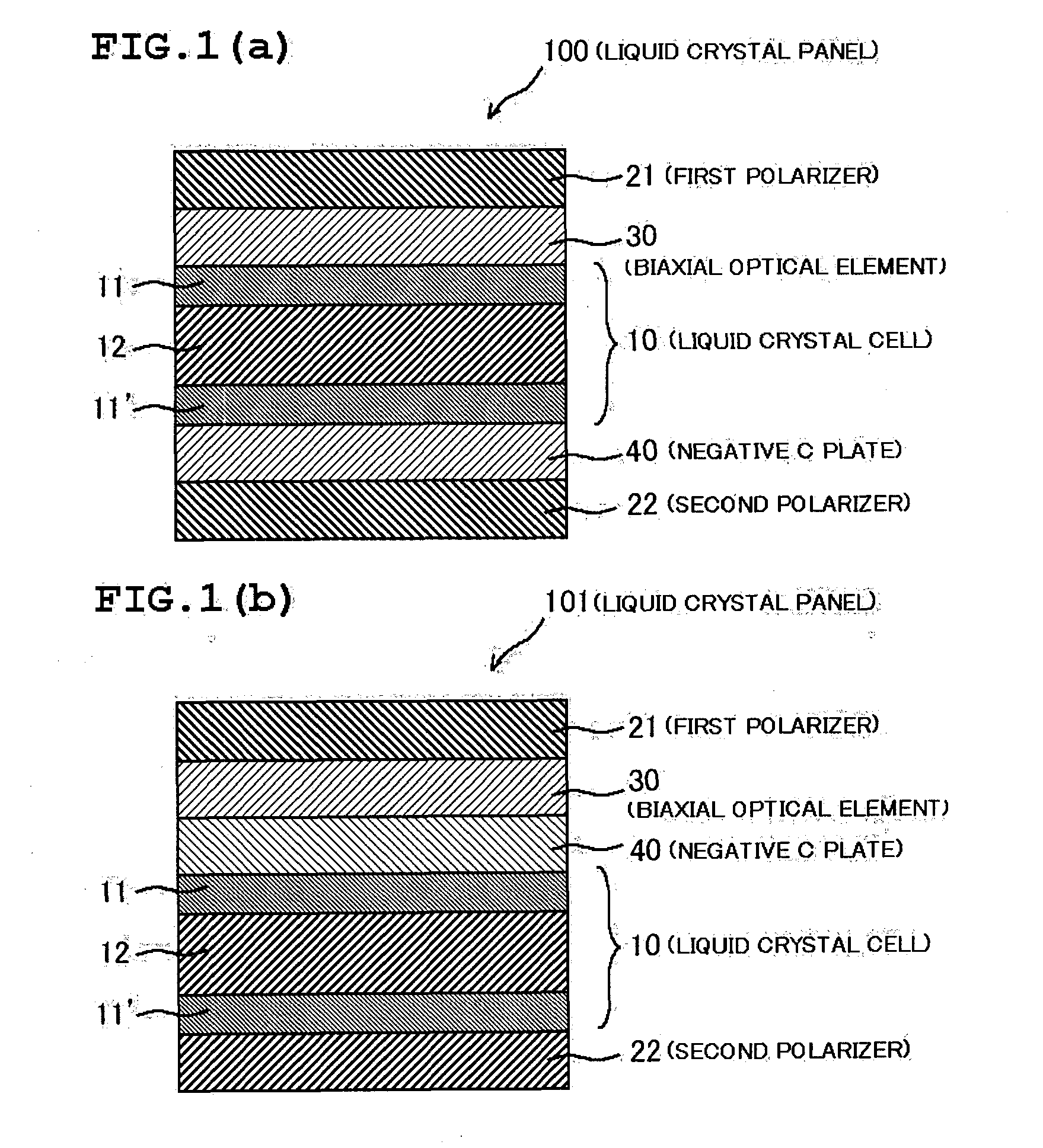
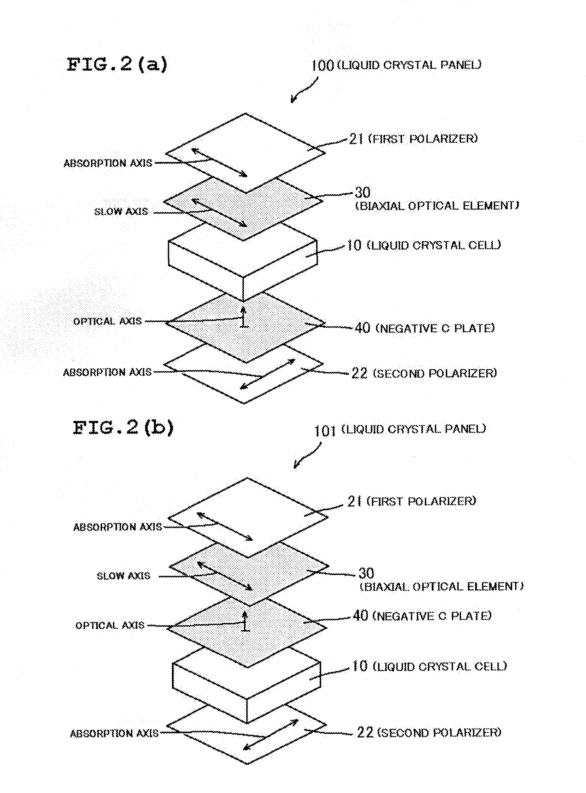
Liquid crystal panel and liquid crystal display apparatus
- Summary
- Abstract
- Description
- Claims
- Application Information
AI Technical Summary
Benefits of technology
Problems solved by technology
Method used
Image

Examples
reference example 1
[0255]A commercially available polarizing plate [trade name “SIG 1423DU” manufactured by Nitto Denko Corporation] was used as it was. The polarizing plate includes a polarizer and a protective layer placed on each of both sides of the polarizer. The above protective layer substantially has isotropy, and has Re[590] of 0.5 nm and Rth[590] of 1.0 nm. Table 1 shows the characteristics of the above polarizing plate.
TABLE 1Reference Example 1P1, P2Single axis transmittance (%)42.6Degree of polarization (%)99.99Hue a value−1.5Hue b value3.8MaterialIodine-containing polyvinyl alcohol
[0256]
reference example 2
[0257]A shrinkable film A (biaxial stretched film having a thickness of 60 μm and containing polypropylene [trade name “Torayfan B02873” manufactured by Toray Industries, Inc.]) was stuck to each of both sides of a polymer film having a thickness of 100 μm and containing a resin obtained by hydrogenating the ring-opened polymer of a norbornene-based monomer (norbornene-based resin) [trade name “ZEONOR ZF-14-100” (average refractive index=1.52, Tg=136° C., 3.0 nm, Rth[590]=5.0 nm) manufactured by OPTES INC.] through an acrylic pressure-sensitive adhesive layer (having a thickness of 15 μm). After that, the resultant film was stretched with a roll stretching machine at a magnification of 1.38 in an air-circulating oven at 146° C. while the film was held in its longitudinal direction. After the stretching, the above shrinkable film A was peeled together with the above acrylic pressure-sensitive adhesive layer, whereby a retardation film 1-A was produced. Table 2 shows the characteristi...
reference example 3
[0258]A shrinkable film B (biaxial stretched film having a thickness of 60 μm and containing polypropylene [trade name “Torayfan BO2570A” manufactured by Toray Industries, Inc.]) was stuck to each of both sides of a polymer film having a thickness of 55 μm and containing a polycarbonate-based resin [trade name “ELMEC” (weight average molecular weight=60,000, average refractive index=1.53, Tg=136° C., Re[590]=1.0 nm, Rth[590]=3.0 nm) manufactured by Kaneka Corporation] through an acrylic pressure-sensitive adhesive layer (having a thickness of 15 μm). After that, the resultant film was stretched with a roll stretching machine at a magnification of 1.26 in an air-circulating oven at 147° C. while the film was held in its longitudinal direction. After the stretching, the above shrinkable film B was peeled together with the above acrylic pressure-sensitive adhesive layer, whereby a retardation film 1-B was produced. Table 2 shows the characteristics of the film. The refractive index ell...
PUM
 Abstract
Description
Claims
Application Information