Projection optical system and projection-type image display apparatus
a projection optical system and image display technology, applied in the field of new projection optical system and new projection type image display apparatus, can solve the problems of increasing sag, difficult manufacture of convex reflectors, and inevitably enlarge the convex reflector f of projection optical system, and achieve the effect of sufficient optical performan
- Summary
- Abstract
- Description
- Claims
- Application Information
AI Technical Summary
Benefits of technology
Problems solved by technology
Method used
Image
Examples
first embodiment
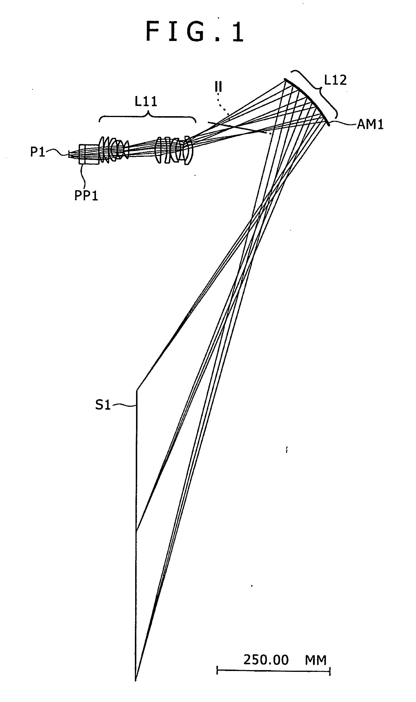
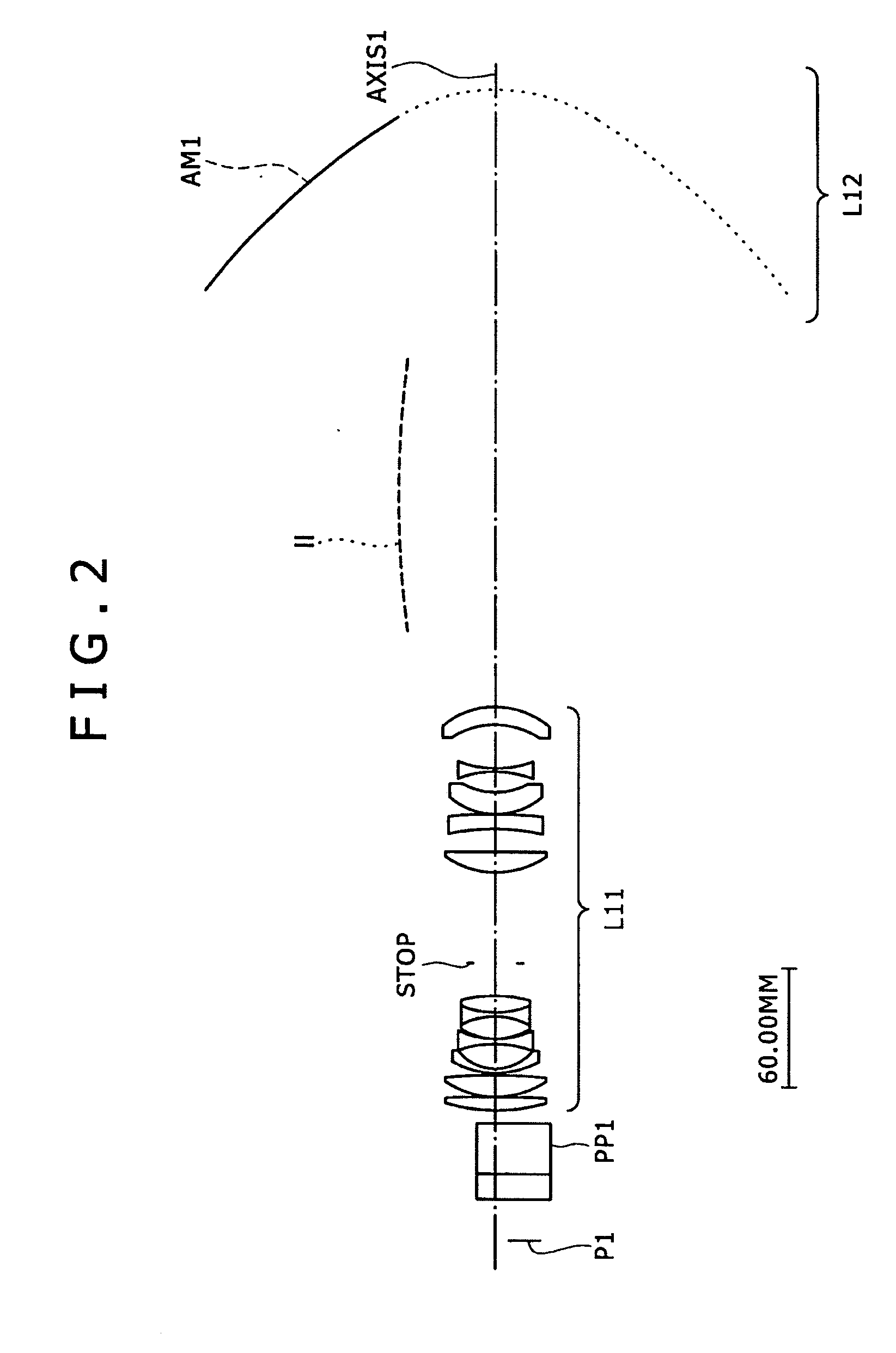
[0125]FIG. 1 outlines the entire optical system of a projector (projection-type image display apparatus) using the projection optical system according to a first embodiment of the invention. FIG. 2 shows an enlarged view of the projection optical system.
[0126]In the diagram illustrating the first embodiment, P1 denotes an image display element as the modulation means. Based on a video signal, the image display element P1 modulates the light emitted from a light source (not shown) to form the primary image surface. The image display element P1 can represent a reflective or transmissive dot-matrix liquid crystal panel, a digital micro mirror device (DMD), and the like. In the diagram, PP1 denotes a polarizing beam splitter (PBS), a 4P prism, a TIR (Total Internal Reflector) prism, and the like. STOP denotes a diaphragm. While the projector needs an illumination optical system to illuminate the image display element P1, the illumination optical system is omitted from FIGS. 1, 2, and th...
second embodiment
[0136]FIG. 10 outlines the entire optical system of a projector (projection-type image display apparatus) using the projection optical system according to a second embodiment of the invention. FIG. 11 shows an enlarged view of the projection optical system.
[0137]In the diagram illustrating the second embodiment, P2 denotes an image display element as the modulation means. Based on a video signal, the image display element P2 modulates the light emitted from a light source (not shown) to form the primary image surface. The image display element P2 can represent a reflective or transmissive dot-matrix liquid crystal panel, a digital micro mirror device (DMD), and the like. In the diagram, PP2 denotes a polarizing beam splitter (PBS), a 4P prism, a TIR (Total Internal Reflector) prism, and the like. STOP denotes a diaphragm. While the projector needs an illumination optical system to illuminate the image display element P2, the illumination optical system is omitted from FIGS. 10, 11, ...
third embodiment
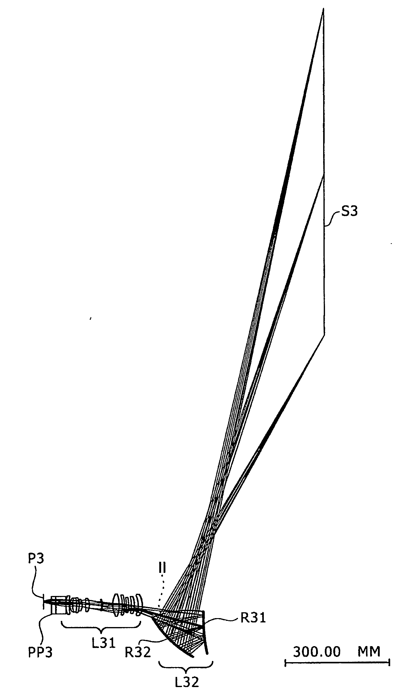
[0150]FIG. 20 outlines the entire optical system of a projector (projection-type image display apparatus) using the projection optical system according to a third embodiment of the invention. FIG. 21 shows an enlarged view of the projection optical system.
[0151]In the diagram illustrating the third embodiment, P3 denotes an image display element as the modulation means. Based on a video signal, the image display element P2 modulates the light emitted from a light source (not shown) to form the primary image surface. The image display element P3 can represent a reflective or transmissive dot-matrix liquid crystal panel, a digital micro mirror device (DMD), and the like. In the diagram, PP3 denotes a polarizing beam splitter (PBS), a dichroic prism, a TIR (Total Internal Reflector) prism, and the like. STOP denotes a diaphragm. While the projector needs an illumination optical system to illuminate the image display element P3, the illumination optical system is omitted from FIGS. 20, ...
PUM
 Abstract
Description
Claims
Application Information
 - R&D
- Intellectual Property
- Life Sciences
- Materials
- Tech Scout
- Unparalleled Data Quality
- Higher Quality Content
- 60% Fewer Hallucinations
Browse by: Latest US Patents, China's latest patents, Technical Efficacy Thesaurus, Application Domain, Technology Topic, Popular Technical Reports.
© 2025 PatSnap. All rights reserved.Legal|Privacy policy|Modern Slavery Act Transparency Statement|Sitemap|About US| Contact US: help@patsnap.com


