Speaker and method of producing the same

a technology of loudspeakers and sonic components, applied in the field of loudspeakers, can solve the problems of reducing sound pressure, adverse effects, performance degradation, etc., and achieve the effects of reducing noise, reducing noise, and improving sound quality

Active Publication Date: 2009-09-17
PANASONIC CORP
View PDF3 Cites 10 Cited by
  • Summary
  • Abstract
  • Description
  • Claims
  • Application Information

AI Technical Summary

Benefits of technology

[0008]The present invention provides loudspeakers excellent in both quality and performance by solving such existing problems by eliminating magnetic flux leakage, and provides manufacturing method of such loudspeakers.
[0011]According to the present invention as described above, by providing at each corner a tongue-like flange that outwardly projects at a position below the top end of the yoke by a predetermined distance and insert molding the yoke into a resin frame in a manner covering the tongue-like flanges, it becomes possible not only to greatly enhance the bonding strength between the yoke and frame but also to obtain a low profile. Also, by making the rectangular yoke in the shape of a dish, clearance at each corner is eliminated thus removing magnetic flux leakage and giving the advantage of stably providing loudspeakers which are excellent both in quality and performance.

Problems solved by technology

Accordingly, magnetic flux leakage takes place from the clearances resulting in performance degradation such as reduction in the sound pressure due to reduction in magnetic flux density.
There is also a fear of an adverse effect being caused by leakage magnetic flux on other electronic components densely mounted in the vicinity of the loudspeaker.

Method used


Image

  • Speaker and method of producing the same
  • Speaker and method of producing the same
  • Speaker and method of producing the same

Examples


first preferred embodiment

[0037]A description of the present invention is given below in terms of the first preferred embodiment.

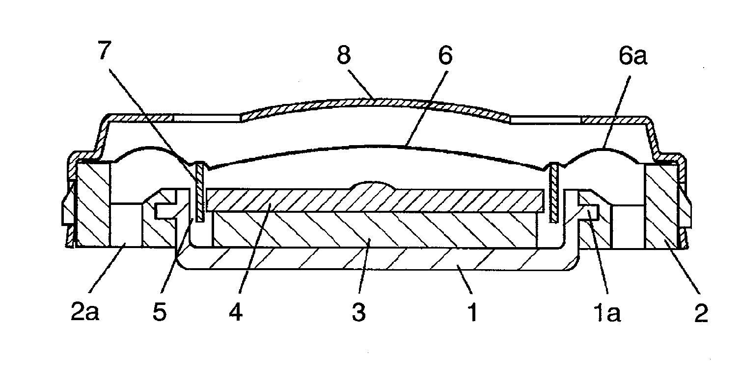
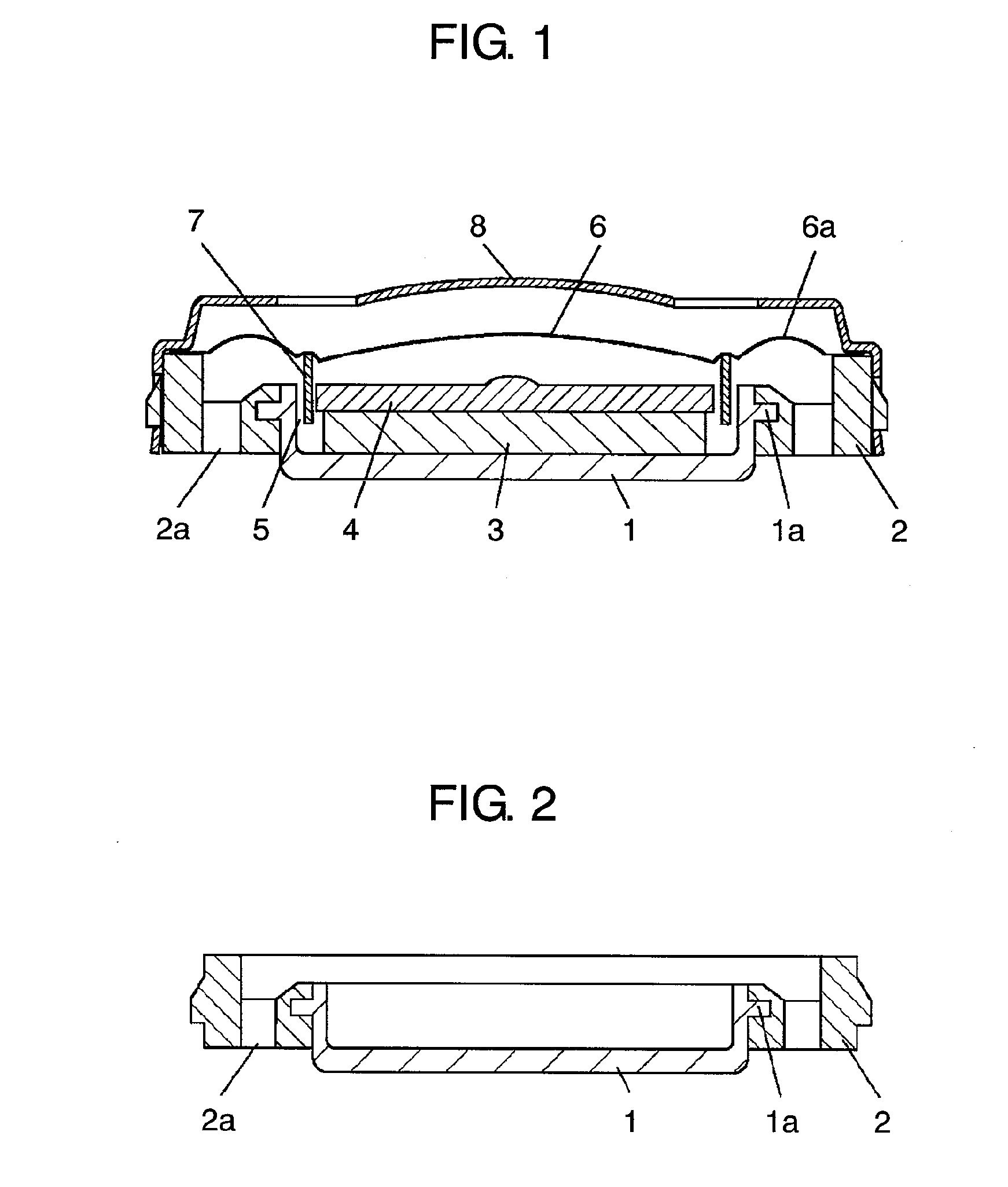
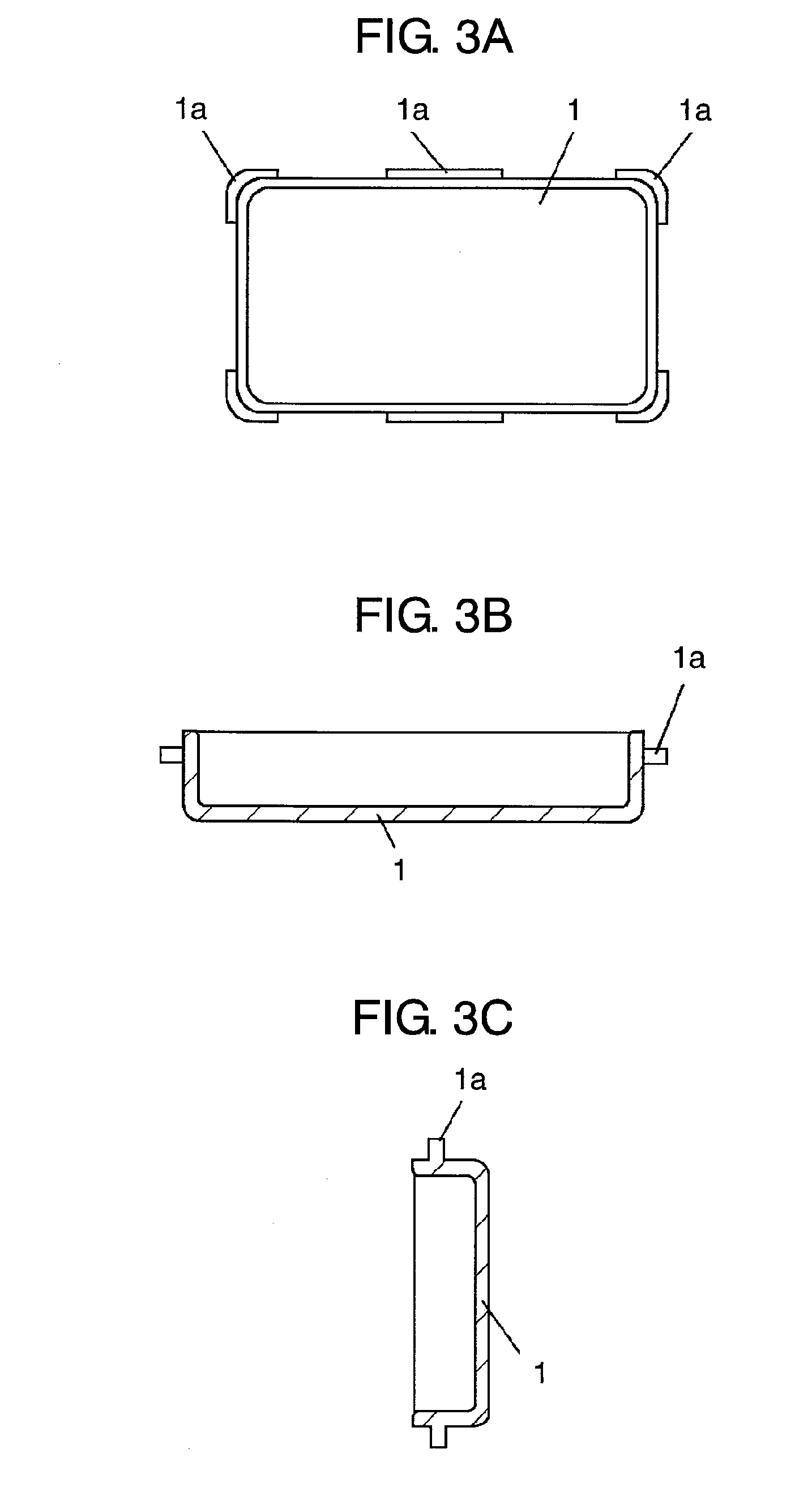
[0038]FIG. 1 is a cross-sectional view showing the structure of a loudspeaker obtained by the method of manufacturing loudspeakers in accordance with the first preferred embodiment of the present invention. FIG. 2 is a cross-sectional view showing a frame in which a yoke used in the loudspeaker is insert-molded. FIG. 3A, FIG. 3B, and FIG. 3C are, respectively, plan view, front cross-sectional view, and side cross-sectional view of the yoke used in the loudspeaker. In FIG. 1, FIG. 2, FIG. 3A, FIG. 3B, and FIG. 3C, yoke 1 is formed into the shape of a rectangular dish using a magnetic metallic material. Also, tongue-like flange la that projects outwardly from a position below the top end surface of yoke 1 by a predetermined distance is symmetrically provided at each corner and on the long sides. By providing the flanges at a position lowered by a predetermined distance, yoke 1 can be...

second preferred embodiment

[0048]A description of the present invention will be given below referring to the second preferred embodiment.

[0049]In the second preferred embodiment, the structure of the voice coil used in the loudspeaker is different from that used in the first preferred embodiment. As other structures are the same as those in the first preferred embodiment, elements similar to those in the first preferred embodiment are given the same reference numbers and detailed description of those elements are omitted, and description will be given only on the different elements referring to drawings.

[0050]FIG. 5 is a cross-sectional view showing the structure of a loudspeaker obtained by the method of manufacturing loudspeakers in the second preferred embodiment of the present invention. In FIG. 5, voice coil 9 is formed by forming a wound coil of a predetermined pattern on the top and rear sides of a resin base material.

[0051]The base material of voice coil 9 excluding the coil is joined to the center of...


PUM

PropertyMeasurementUnit
degree of freedomaaaaaaaaaa
magnetic fieldaaaaaaaaaa
shapeaaaaaaaaaa

Abstract

A plate material is drawn into the shape of a rectangular dish and the peripheral border of each corner is press worked. A yoke is fabricated which has an outwardly projecting tongue-like flange provided at a position a predetermined distance below the top end surface. A frame made of resin is insert molded in a manner covering the flange. A magnet is secured inside the yoke and a magnetic circuit having magnetic gap is formed. A diaphragm joined with a voice coil is joined with the frame. By making a loudspeaker in this way, the bonding strength between the yoke and the frame is enhanced and a low-profile loudspeaker is achieved. Also, clearance at each corner of the yoke is eliminated, and a loudspeaker that is free from magnetic flux leakage and excellent both in quality and performance is obtained.

Description

TECHNICAL FIELD[0001]The present invention relates to loudspeakers to be used in various audio devices and communications devices, more specifically to small, thin and rectangular loudspeakers for use in mobile phones where loudspeaker mounting space is limited, and to manufacturing method of the loudspeakers.BACKGROUND ART[0002]Along with the trend toward miniaturization and multi-functioning of various audio devices and communications devices, miniaturization of loudspeakers to be used in these devices is increasingly accelerated. Especially for loudspeakers to be used in mobile phones, not only miniaturization but also high-quality sound is required. Under such circumstances, emphasis of loudspeaker development is placed on rectangular loudspeakers rather than more general circular loudspeakers to enable more efficient use of limited space available in mobile phones where loudspeaker mounting space is limited.[0003]FIG. 6 is a cross-sectional view showing structure of a conventio...

Claims


Application Information

Patent Timeline
Patent Type & Authority Applications(United States)
IPC IPC(8): H04R1/00H04R31/00
CPCH04R31/006Y10T29/49005H04R2209/024
Inventor TAKASE, TOMOYASUENOMOTO, MITSUTAKAYAMASAKI, KAZUYAKUBO, KAZUTAKASUMIYAMA, MASAHIDE
Owner PANASONIC CORP
Why Eureka
Try Eureka