Connection structure of two-dimensional array optical element and optical circuit

a technology of two-dimensional array and connection structure, applied in the direction of optical elements, instruments, optical waveguide light guides, etc., can solve the problems of large thickness and difficult to connect structures as a whole, and achieve the effect of reducing the size of the connection structure, efficient connection to each other, and reducing the profil

Inactive Publication Date: 2009-09-17
NEC CORP +1
View PDF21 Cites 10 Cited by
  • Summary
  • Abstract
  • Description
  • Claims
  • Application Information

AI Technical Summary

Benefits of technology

[0006]It is a first object of the present invention to solve the problems of the related art described above, overcome the limited parallelism that has existed in a connection structure using a one-dimensional array of the related art, and greatly increase the parallelism, i.e., greatly increase the number of connections. A second object of the present invention is to provide a low-profile connection structure for connecting a two-dimensional array of optical elements and optical circuits, which can be laid parallel along a substrate on which devices such as LSI circuits are mounted.
[0011]Of the optical circuits in the layers, adjacent layers may have a common cladding layer. The optical circuits may be disposed on a surface of a substrate in which the optical element is embedded. The optical elements may be mounted in cavities defined in the optical circuits. These arrangements are effective to make the connection structure lower in profile.
[0013]According to the present invention, a plurality of optical elements arranged in a two-dimensional array and optical circuits can efficiently be connected to each other, and the size of a connection structure can be reduced and its profile lowered.

Problems solved by technology

These connection structures have been problematic in that they are thick as a whole due to a limitation posed by the minimum bend radius of optical fiber array 6 (see IEICE Transactions C, Vol.

Method used


Image

  • Connection structure of two-dimensional array optical element and optical circuit
  • Connection structure of two-dimensional array optical element and optical circuit
  • Connection structure of two-dimensional array optical element and optical circuit

Examples


exemplary embodiment 1

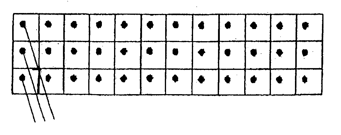
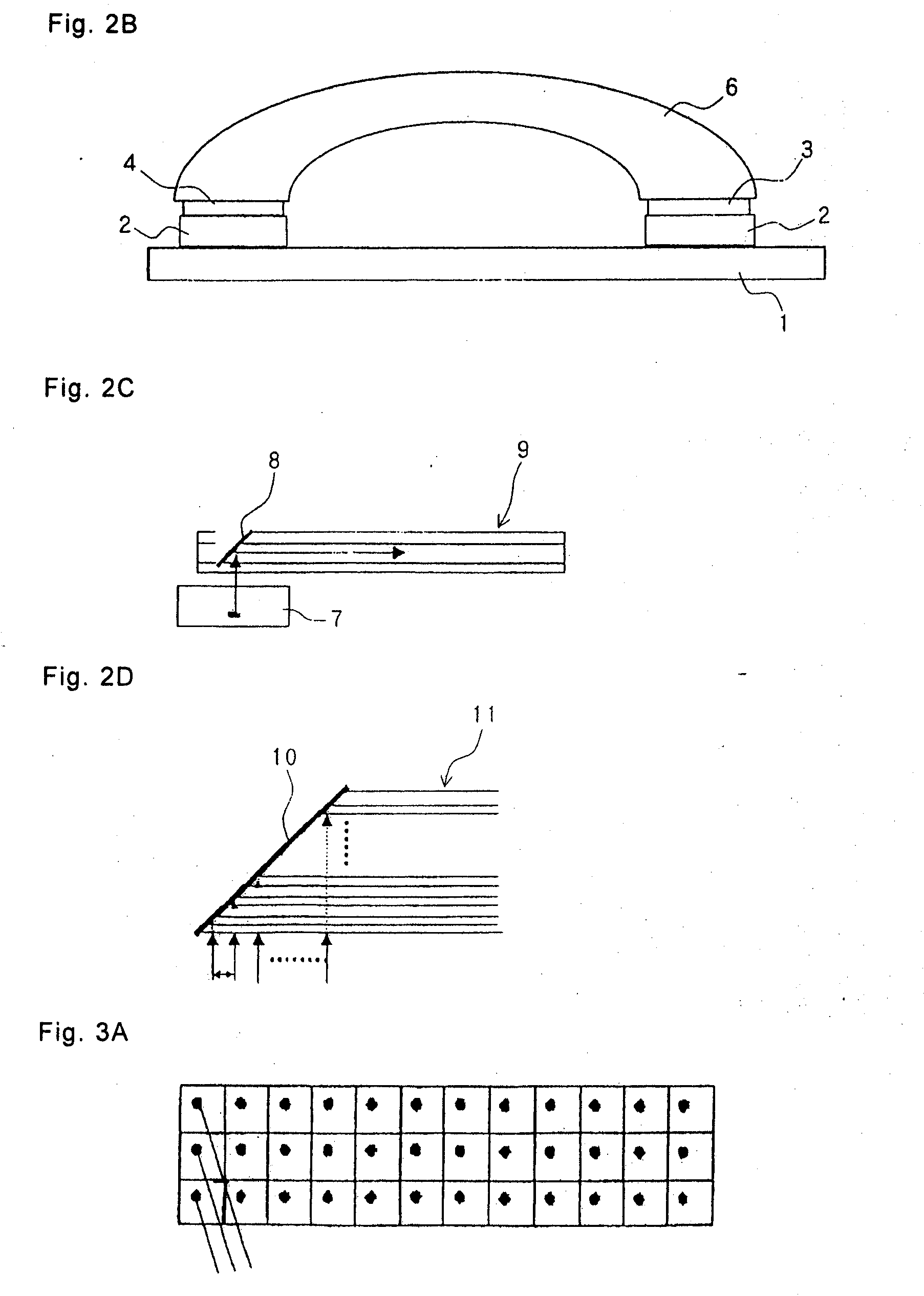
[0055]FIGS. 3A through 3D show Exemplary embodiment 1 of the present invention. FIG. 3A schematically shows a two-dimensional array of optical elements, FIG. 3B is an enlarged view of FIG. 3A, FIG. 3C is a cross-sectional view taken along line A-A′ of FIG. 3B, and FIG. 3D is a cross-sectional view taken along line B-B′ of FIG. 3B.

[0056]According to the present exemplary embodiment, an array of optical waveguides 12 is inclined obliquely to a two-dimensional array of optical elements 16 such as light sources or the like. This arrangement makes it possible to connect a group of optical waveguides to an array of optical elements in three rows, rather than to an array of optical elements in one row which has heretofore been possible (see FIG. 3C). As shown in FIG. 3D, light sources 16 and optical waveguides 12 are connected to each other by micromirrors 15 comprising 45° plane reflecting mirrors or curved reflecting mirrors disposed in portions of optical waveguides 12 for bending light...

exemplary embodiment 2

[0060]FIG. 5A shows Exemplary embodiment 2 of the present invention. According to Exemplary embodiment 2, a basic structure comprises a one-dimensional array of micromirrors 15 and optical waveguides 12 connected thereto, and a plurality of such basic structures are stacked with adjacent basic structures being shifted from each other by a length of one row of optical element array. Optical waveguides 12 are connected to a two-dimensional array of optical elements 16. If each optical waveguide 12 comprises core 13 having a diameter of 50 μm and cladding having a thickness of 25 μm on each side of core 13, then one layer (one step) of optical waveguides 12 has a thickness of 100 μm. Therefore, provided that the light beams from optical elements 16 are appropriately shaped, it is possible to stack optical waveguides 12 in five to ten layers. If one array of optical elements contains 20 optical elements, then about 100 to 200 multiplex parallel light connections can be achieved between ...

exemplary embodiment 3

[0063]FIG. 6 shows Exemplary embodiment 3 of the present invention. According to Exemplary embodiment 3, the structure according to Exemplary embodiment 1 is stacked in multiple layers with adjacent basic structures being shifted from each other by a length of one row of optical element array. According to Exemplary embodiment 3, it is possible to provide parallel multiplex light connections in a higher packing density than according to Exemplary embodiment 2.

[Analysis of Optical Coupling]

[0064]The results of an analysis of an optical coupling among VCSELs 16, micromirrors 15, and optical waveguides 12 will be described below.

[0065]As shown in FIG. 7A, calculations were carried out on the assumption that a Gaussian beam is emitted from VCSEL 16. The spot size of the emitted beam from VCSEL 16 is spread as shown in FIG. 7A. The spot size W0 is represented by the radius of the emitted beam as shown in FIG. 7A. The spot size W(z) is calculated according to the following equation:

w(z)=[...


PUM


Abstract

Optical elements (light sources 16 or photodetectors 18) are arranged in a two-dimensional array, and the relative positional relationship between the optical elements and optical waveguides 12 is defined such that optical waveguides 12 extend between the optical elements in the two-dimensional array substantially parallel to substrate 19 for increased parallelism. Micromirrors 15 are disposed in respective optical waveguides 12 to bend light beams through 90 degrees to realize a highly efficient optical coupling between the optical elements and optical waveguides 12. The optical waveguides are stacked in multiple stages, and light beams are lead to the optical waveguides in the multiple stacks through micromirrors 15 across the stacked plane of the optical waveguides, thereby realizing parallel connection between the two-dimensional array of optical elements and a two-dimensional array of optical waveguides. There is thus provided a connection structure between the optical elements and optical waveguides 12, which is small in size and high in efficiency, and is of high parallelism.

Description

TECHNICAL FIELD[0001]The present invention relates to a connection structure for connecting a two-dimensional array of optical elements and optical circuits.BACKGROUND ART[0002]One example of a so-called optical interconnection structure for connecting semiconductor chips, primarily high-speed LSI circuits, with an optical signal is shown in FIGS. 1A and 1B. In this structure, LSI circuits 2 on substrate 1 are connected to each other by thin optical waveguide 5 parallel to substrate 1 through PD (PhotoDiode: light-detecting device) 3 and VCSEL (Vertical Cavity Surface-Emitting Laser) 4. In the example shown in FIGS. 1A and 1B, interposers 1a are provided. The number of general connections (parallelism) is in the range from about 100 to 1000. An optical circuit generally refers to an optical fiber, an optical waveguide, and a combination of an optical fiber and an optical waveguide.[Related Art 1][0003]It has heretofore been customary to optically connect a number of light sources an...

Claims


Application Information

Patent Timeline
Patent Type & Authority Applications(United States)
IPC IPC(8): G02B6/12H01L33/00H01L33/08H01L33/58H01L33/60
CPCG02B6/4214G02B6/3676G02B6/43G02B6/4249
Inventor ODA, MIKIOKOUTA, HIKARUNAKANO, KAICHIROUTAKAHASHI, HISAYAKOBAYASHI, KOHROH
Owner NEC CORP
Why Eureka
Try Eureka