Joint for a motor vehicle

a technology for connecting parts and motor vehicles, applied in mechanical devices, sliding contact bearings, couplings, etc., can solve the problems of inability to reproduce, inability to set prestress very finely, and inability to acceptably large clearance, etc., and achieve the effect of finer torque setting

Inactive Publication Date: 2009-09-17
ZF FRIEDRICHSHAFEN AG
View PDF10 Cites 16 Cited by
  • Summary
  • Abstract
  • Description
  • Claims
  • Application Information

AI Technical Summary

Benefits of technology

[0008]The object of the present invention is to perfect a joint of the type

Problems solved by technology

2 Nm and is intentionally generated by press fit (oversize) of the ball in the ball shell, because an unacceptably great clearance would otherwise develop already after a slight wear or in case of tolerance deviations.
However, the effect is only marginal (an up to 3-fold increase in torque can be obtained) and is not always reproducible.
However, the prestress cannot be set very finely in the case of such a ball and socket joint, because even motions in the range of one hundredths of one mm lead to very great changes in torque.
Fur

Method used


Image

  • Joint for a motor vehicle
  • Joint for a motor vehicle
  • Joint for a motor vehicle

Examples


first embodiment

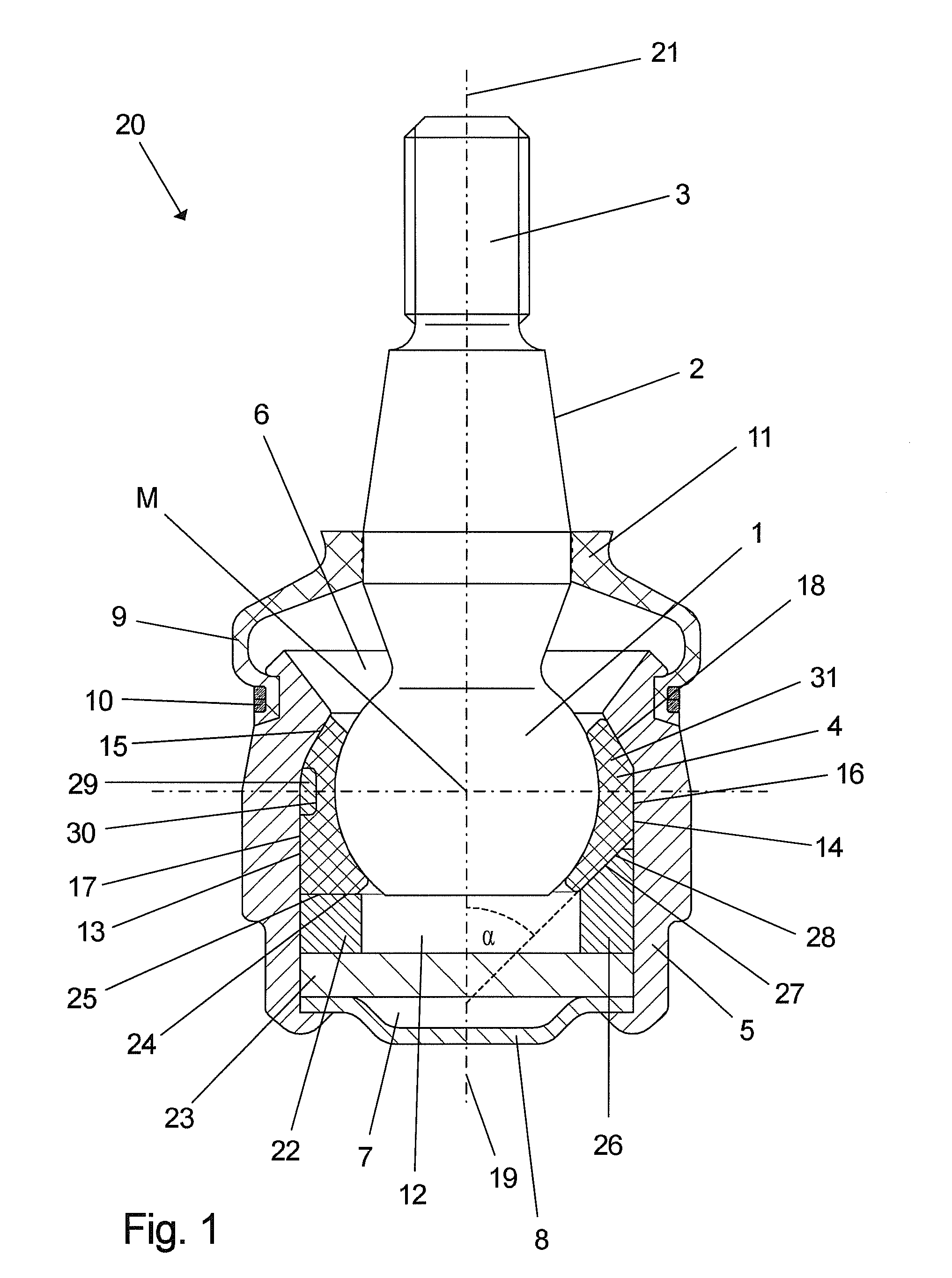
[0038]According to the present invention, a preferably ring-shaped tensioning means 22 is arranged between the bearing shell 4 and the cover 8 via the intermediary of a thrust ring 23. The tensioning means 22 is in contact by a surface area 24 with an outer surface area 25 of the bearing shell 4, the thrust ring 23 being arranged between the tensioning means 22 and the cover 8. The tensioning means 22 is designed here, for example, as an electrically actuated, piezoelectric actuator, which can deform the bearing shell 4 in parallel to the longitudinal axis 19 due to a change in length. The mechanical stress exerted by the bearing shell 4 on the joint ball 1 is changed as a result, so that the torque necessary for pivoting the ball pivot 3 can be set by means of a change in the length of the tensioning element or by means of a change in the electric voltage present on the said tensioning element. The surface area 24 and the outer surface area 25 extend at right angles to the longitud...

third embodiment

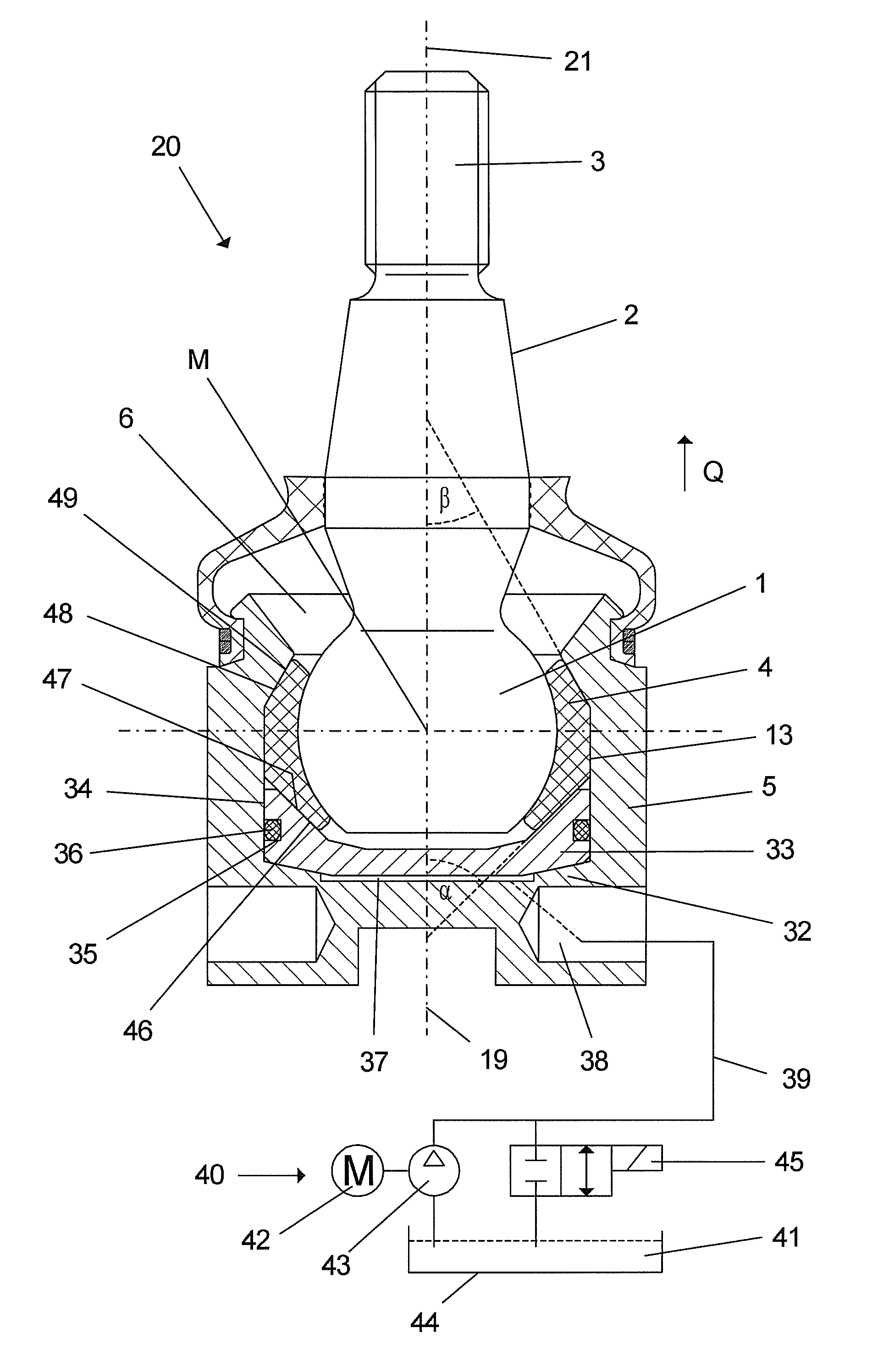
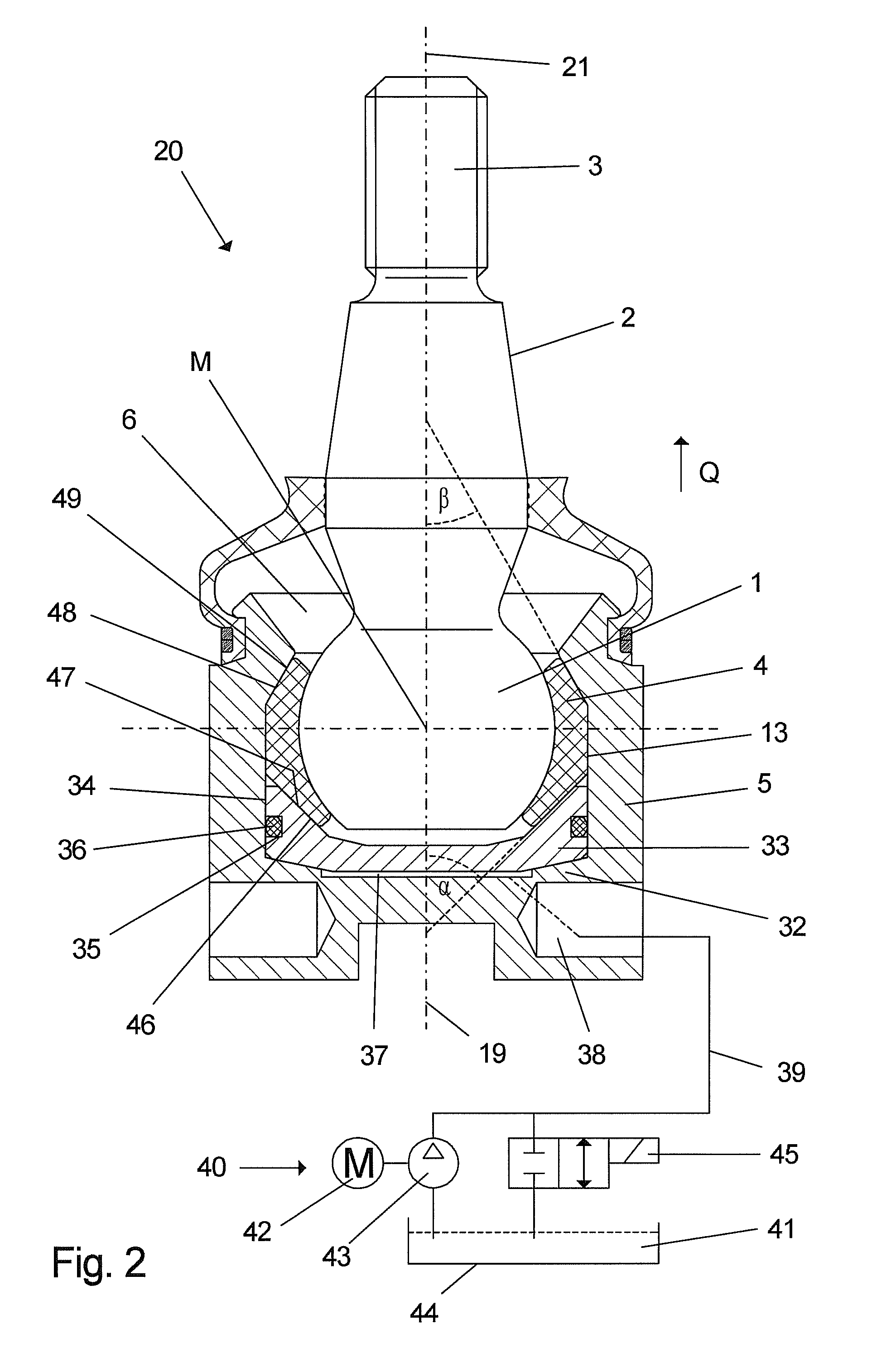
[0040] a tensioning means 29, which is arranged in the radial direction between the bearing shell 4 and the inner wall 13 of the housing 5, is provided in addition or as an alternative to the tensioning means 22. The tensioning means 29 is seated in a recess 30 of the bearing shell 4, but may also be arranged, as an alternative, in a recess formed in the inner wall 13. It is possible by means of the tensioning means 29 to build up a stress acting on the joint ball 1 primarily in the radial direction, “radial direction” being defined here as a direction that extends at right angles to the longitudinal axis 19 and preferably intersects the center M of the joint ball 1. The tensioning means 29 may be designed as a piezoelectric actuator, which can be controlled by means of an electric voltage, can deform the bearing shell 4 in the radial direction by a change in length and can thus change the mechanical stress exerted by the bearing shell 4 on the joint ball 1.

fourth embodiment

[0041] the bearing shell may be manufactured, in addition or as an alternative to the previous embodiments, completely or at least in some areas, of an electrically deformable composite 31, which consists, for example, of a plastic with piezoceramic fibers or carbon nanotubes, which are embedded therein and form a tensioning means. By applying an electric voltage to the bearing shell 4, deformation or a change in the volume of the bearing shell can be brought about, which leads to a change in the mechanical stress exerted by the bearing shell 4 on the joint ball 1. The bearing shell 4 itself thus forms an actuator.

[0042]The effect on the torque is controlled actively in the first four embodiments, and an actuator, which can be actuated especially electrically, is used as the tensioning means. A force is exerted on the bearing shell 4 and hence on the joint ball 1 due to a change in the length or an expansion of the actuator, as a result of which the momentum of the body of the ball ...


PUM

PropertyMeasurementUnit
Magnetic fieldaaaaaaaaaa
Areaaaaaaaaaaa
Surface areaaaaaaaaaaa

Abstract

A joint for a motor vehicle is provided with a housing (5), a bearing shell (4) arranged in the housing (5), a bearing journal (3), which has a bearing area (1) and a pivot area (2) and which is mounted pivotably and/or rotatably in the bearing shell (4) with the bearing area (1). The joint has at least one tensioning device (33), which is arranged in the housing 5, is designed as a solid body and by which a mechanical stress exerted by the bearing shell 4 on the bearing area 1 can be changed. The bearing shell 4 is springy at least in some areas and is deformable by the tensioning means 33 in a springy manner.

Description

CROSS REFERENCE TO RELATED APPLICATIONS[0001]This application is a United States National Phase application of International Application PCT / DE2005 / 000526 filed Mar. 22, 2005, the entire contents of which are incorporated herein by reference.FIELD OF THE INVENTION[0002]The present invention pertains to a joint for a motor vehicle, with a housing, a bearing shell arranged in the housing, a bearing journal, which has a bearing area and a pivot area, and which is mounted pivotably and / or rotatably with the bearing area in the bearing shell, and at least one tensioning means, which is arranged in the housing, is designed as a solid body and by which a mechanical stress exerted by the bearing shell on the bearing area can be changed.BACKGROUND OF THE INVENTION[0003]Joints, especially ball and socket joints, require a certain torque to move the bearing area or the joint ball. A typical torque is, for example, approx. 2 Nm and is intentionally generated by press fit (oversize) of the ball ...

Claims


Application Information

Patent Timeline
IPC IPC(8): F16C11/06
CPCF16C11/0647Y10T403/32737F16C2202/36F16C2208/20F16C17/24F16C41/00
Inventor ERSOY, METINRECHTIEN, MARTINSPRATTE, JOACHIMBUDDE, FRANKMULLER, ARMIN
Owner ZF FRIEDRICHSHAFEN AG
Why Eureka
Try Eureka