
Compressor-Expander Set Critical Speed Avoidance

a compressor and critical speed technology, applied in the direction of machines/engines, positive displacement liquid engines, lighting and heating apparatus, etc., can solve the problems of vanes contacting the compressor shroud, and the general operation of the turbocompressor at low flow ra

Active Publication Date: 2009-09-17
COMPRESSOR CONTROLS LLC
View PDF5 Cites 68 Cited by
  • Summary
  • Abstract
  • Description
  • Claims
  • Application Information

AI Technical Summary

Benefits of technology

[0016]A purpose of the present invention is to provide a method and apparatus for avoiding operating a compressor-expander set in a critical speed zone longer than a predetermined time while maintaining the process at its set point or set points.
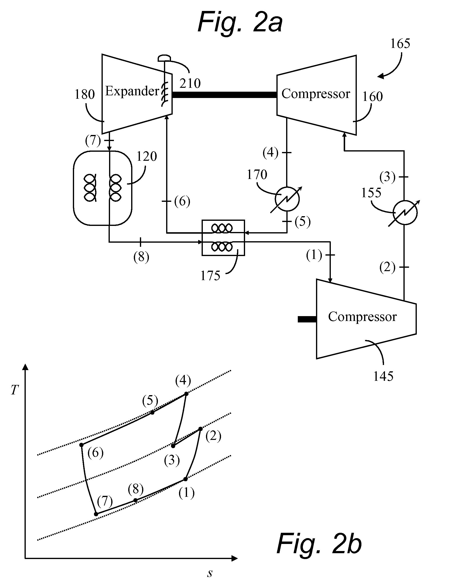
[0023]For most centrifugal compressors over most of the operating range, increased flow rate corresponds to increased power required to drive the compressor. Accordingly, when the recycle valve is opened, the power needed to drive the compressors increases. Even when increased flow rate results in reduced power requirement, such as is common for axial compressors, opening the recycle valve results in a change (a decrease) in power required. Therefore, the recycle valve can be used to predictably vary the rotational speed of the compressor-expander set, even while the expander mass flow rate is maintained at a constant value.
[0025]An additional object of this invention is the use of a feed-forward signal to signal the nitrogen recycle compressor's control system of a compressor-expander set trip. That is, if a compressor-expander goes into shutdown expectedly or unexpectedly, the nitrogen recycle compressor may be driven toward surge. By signaling the nitrogen recycle compressor's control system to open the nitrogen recycle compressor's recycle valve, surge of the nitrogen recycle compressor can be avoided.

Problems solved by technology

Turbocompressors generally experience unstable operation at low flow rates.
The instability takes the form of either stall or surge, with surge being the most common for industrial compressors.
This results in large thrust loads that can damage thrust bearings and cause vanes to contact the compressor shroud.
A challenging aspect for this control system is avoidance of critical speeds for the compressor-expander sets used in the gas refrigeration loop.

Method used


Image

  • Compressor-Expander Set Critical Speed Avoidance
  • Compressor-Expander Set Critical Speed Avoidance
  • Compressor-Expander Set Critical Speed Avoidance

Examples


Embodiment Construction

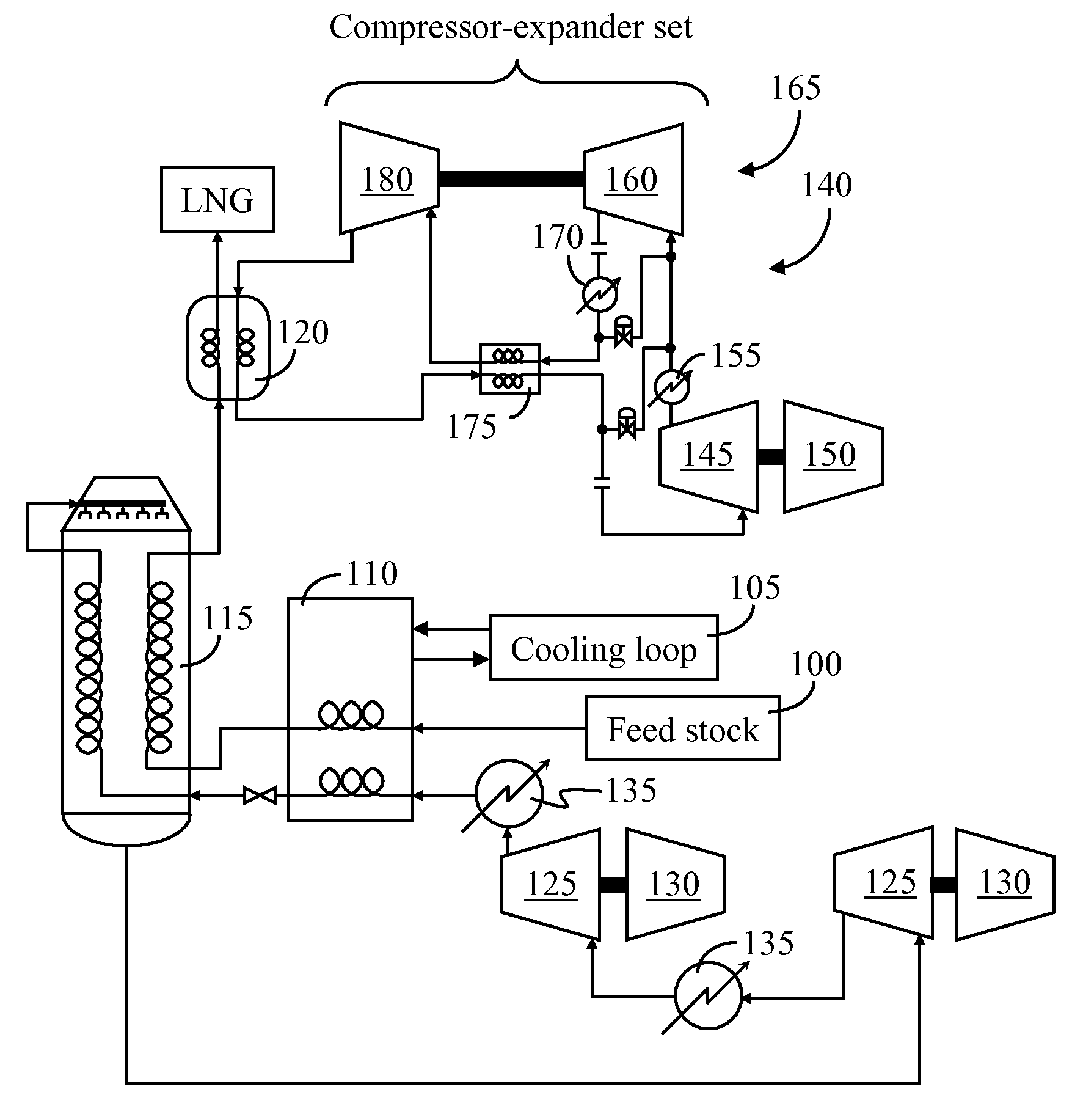
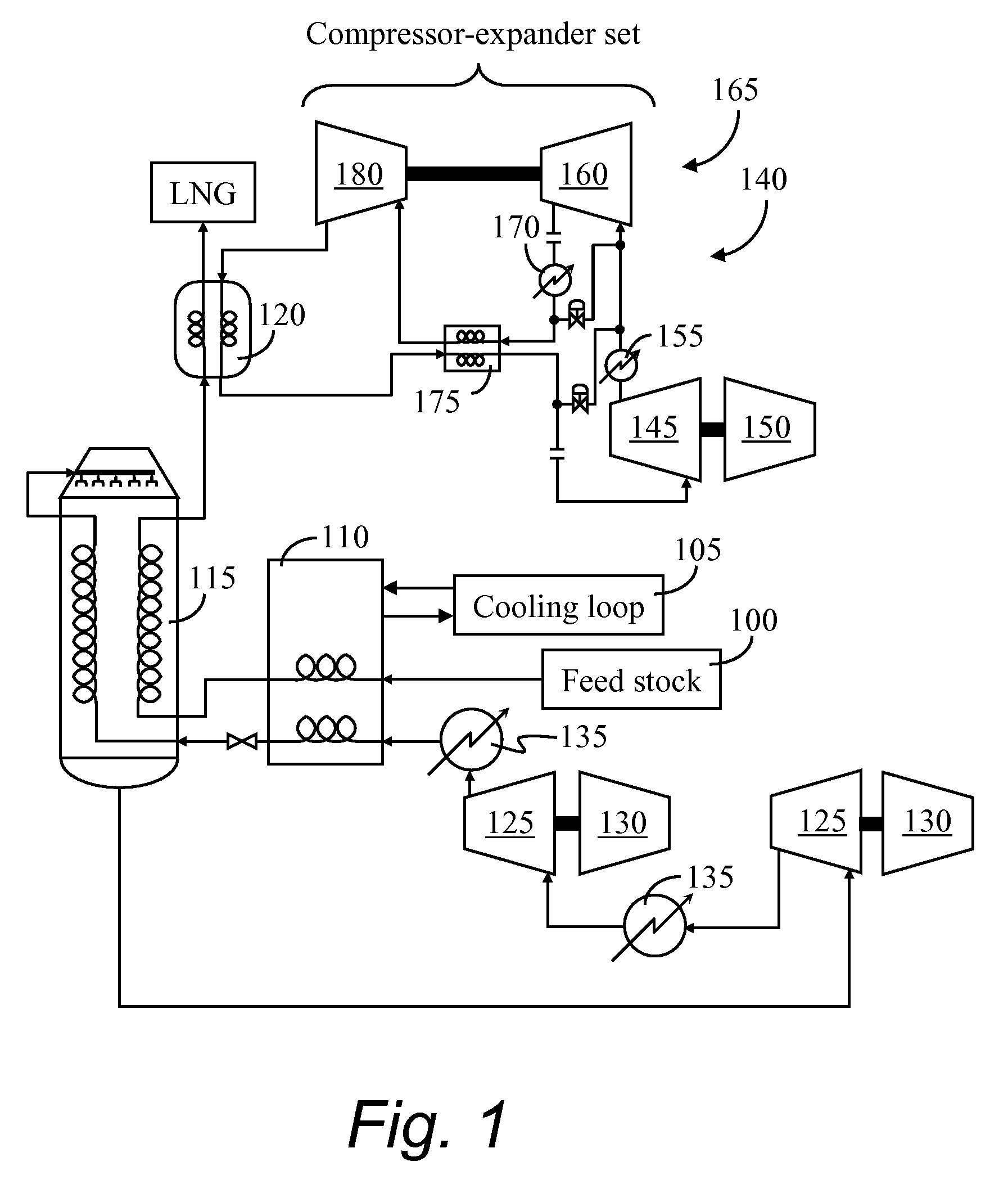
[0042]Referring to FIG. 1, feed stock 100, for this example, natural gas, is first dehydrated (not shown) and the heavy components removed (not shown). A relatively high temperature cooling loop 105 (or plurality of loops) such as a propane refrigeration loop, is used to lower the temperature of the gaseous feedstock 100 in a high temperature heat exchanger 110.

[0043]The feedstock 100 then enters a main heat exchanger 115, where the remainder of the sensible heat is removed, and at least some of the latent heat is also removed from the feedstock 100. The feedstock 100 is further cooled in a subcooling heat exchanger 120 where the temperature of the feedstock 100 is lowered below the saturation temperature. At this point, with very little additional processing, the pressure of the liquid natural gas is dropped and the LNG stream is directed to storage.

[0044]The refrigeration loop providing the low temperature stream in the main heat exchanger 115 is often a mixed refrigerant (MR) ref...


PUM


Abstract

A control method and apparatus for critical rotational speed avoidance in a compressor-expander set in a gas refrigeration system. By varying an opening of an antisurge or recycle valve, a shaft power used by the compressor in the compressor-expander set may be varied, thereby varying the rotational speed of the compressor-expander set to move it away from its critical speed zone. Additionally, a feedforward signal may be provided by a compressor-expander set control system to cause an antisurge valve for a recycle compressor to open upon a trip or shutdown of one compressor-expander set.

Description

BACKGROUND OF THE INVENTION[0001]1. Field of the Invention[0002]The present invention relates generally to a control scheme. More particularly the present invention relates to a method and apparatus for limiting a time of operation in a critical speed zone of turbomachinery. This invention also relates to an antisurge scheme for a recycle compressor when a compressor-expander set trips.[0003]2. Background Art[0004]Most turbomachines, such as compressors, gas turbines, steam turbines, and expanders inherently exhibit at least one critical speed where the rotational speed of the turbomachine excites a natural frequency of the turbomachine. Extended operation at such critical speeds must necessarily be avoided.[0005]When the critical speed or speeds reside below the normal operating region of the turbomachine, a startup procedure involving high angular accelerations through the critical speed or speeds is carried out, thus minimizing the time of operation in a neighborhood of the criti...

Claims


Application Information

Patent Timeline
IPC IPC(8): F04B49/00F04D27/00
CPCF01D21/02F25B31/00F04D25/04F04D27/0261F25B11/02F25J1/0022F25J1/005F25J1/0052F25J1/0072F25J1/0218F25J1/0265F25J1/0271F25J1/0283F25J1/0288F25J1/0294F25J1/0298F25J2240/04F25J2270/16F25J2290/34F04B49/02F25J1/0272F05D2270/021F02C9/18Y02B30/70
Inventor MIRSKY, SAULJACOBSON, WAYNEHOOGERWERF, DAVID J.ISLAM, NAUMAN
Owner COMPRESSOR CONTROLS LLC
Learn More