Particle Radiation Therapy Equipment

a radiation therapy equipment and particle technology, applied in the direction of nmr measurement, therapy, instruments, etc., can solve the problems of difficult manufacturing of described arrangements and the majority of present mri scanners

Active Publication Date: 2009-09-17
SIEMENS HEALTHCARE LTD
View PDF24 Cites 22 Cited by
  • Summary
  • Abstract
  • Description
  • Claims
  • Application Information

AI Technical Summary

Problems solved by technology

This may result in the irradiation of healthy tissue and/or missing diseased tissue, which may lead to a remission.
The majority of present MRI scan

Method used


Image

  • Particle Radiation Therapy Equipment
  • Particle Radiation Therapy Equipment
  • Particle Radiation Therapy Equipment

Examples


Embodiment Construction

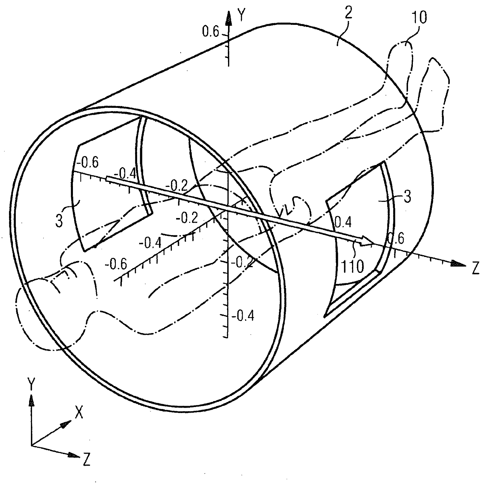
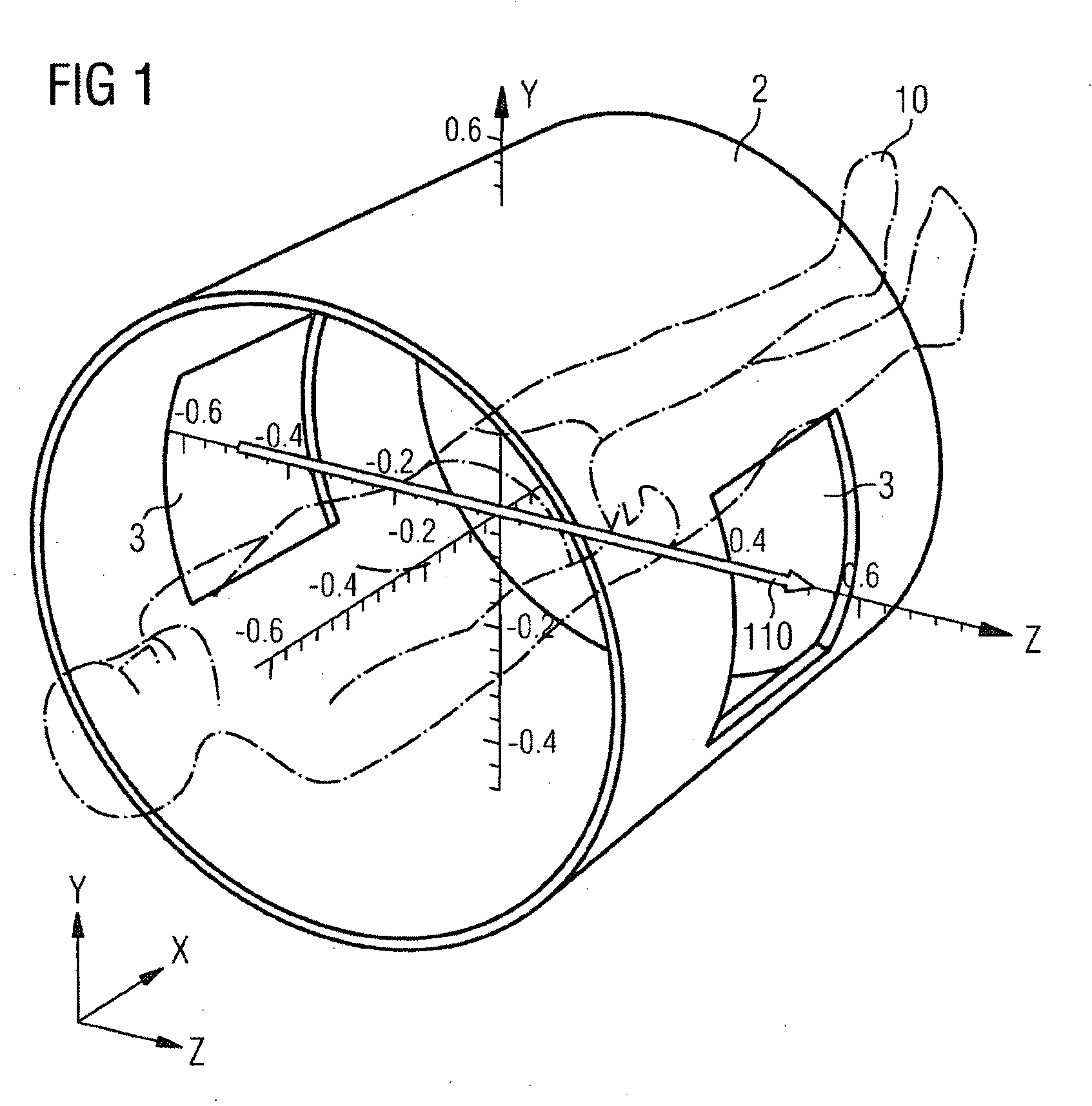
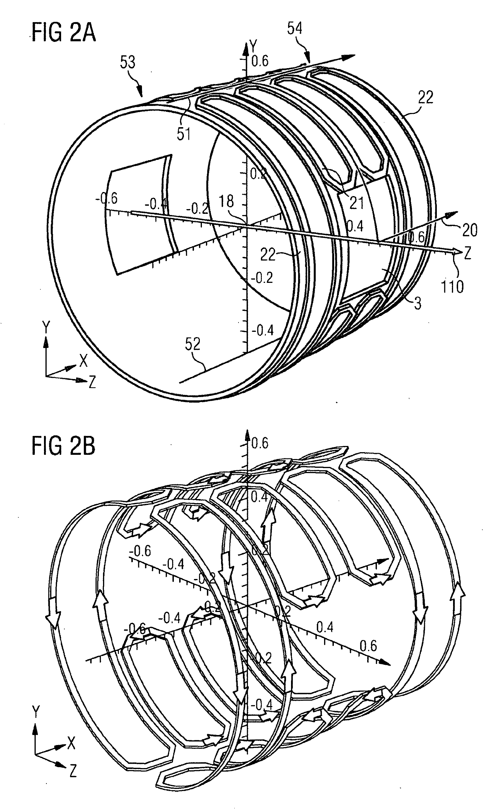
[0022]The present invention provides an application of a novel arrangement of magnet field coils to provide improved particle radiation therapy equipment. According to the present invention, a charged particle beam source is arranged to direct a charged particle beam in a predetermined direction to a region of application. Furthermore, magnetic field generation means are provided for generating a magnetic field in the region of application at the same time that the charged particle beam is applied, wherein the magnetic field generation means is arranged to provide access to the region of application for the charged particle beam, and to provide a homogeneous magnetic field in the region of application of the charged particle beam, said magnetic field being directed substantially in the predetermined direction.

[0023]A field magnet for generating a main magnetic field in an MRI system, according to an aspect of the present invention, is schematically shown in FIG. 1. The magnet consis...


PUM


Abstract

Particle radiation therapy equipment arranged to apply a charged particle beam to a region of application in a predetermined direction, comprising a charged particle beam source arranged to direct a charged particle beam in the predetermined direction, further comprising magnetic field generation means for generating a magnetic field in an imaging volume which includes the region of application at the same time that the charged particle beam is applied, wherein the magnetic field generation means is arranged to provide access to the region of application for the charged particle beam, and to provide a homogeneous magnetic field in the region of application of the charged particle beam, said magnetic field being directed substantially in the predetermined direction.

Description

FIELD OF THE INVENTION[0001]The present invention describes particle radiation therapy equipment which includes a magnet, thereby enabling magnetic resonance imaging (MRI) during particle radiation therapy.BACKGROUND OF THE INVENTION[0002]Radiation therapy with protons and carbon ion beams has been shown to be effective. In addition it has been shown to result in less damage to tissue than conventional gamma radiation therapy.[0003]However, radiation planning for determining the magnitude and position of a dose to be administered is based on MRI imaging or CT imaging, which may have taken place at a considerable time period before the therapy takes place. In the intervening period, the position of the tissue to be irradiated may have moved, or changed shape. This may result in the irradiation of healthy tissue and / or missing diseased tissue, which may lead to a remission.[0004]In ion beam therapy, the patient is in general irradiated with a beam offered in a transverse direction 110...

Claims


Application Information

Patent Timeline
IPC IPC(8): A61B5/055G01V3/00A61N5/10G01R33/381
CPCA61N5/1049A61N5/1067G01R33/381A61N2005/1087A61N2005/1055A61B5/055G01R33/48
Inventor KRUIP, MARCEL JAN MARIE
Owner SIEMENS HEALTHCARE LTD
Why Eureka
Try Eureka