Cache memory control method and cache memory control device

a control method and memory technology, applied in the direction of memory adressing/allocation/relocation, instruments, liquid/fluent solid measurement, etc., can solve the problems of insufficient effect, limited effectiveness of this method, wasteful power consumption state, etc., and achieve the effect of enabling power reduction of cache access without degrading the performance of cache access cycl

Active Publication Date: 2009-09-17
BEIJING ESWIN COMPUTING TECH CO LTD
View PDF9 Cites 5 Cited by
  • Summary
  • Abstract
  • Description
  • Claims
  • Application Information

AI Technical Summary

Benefits of technology

[0026]In a system that is provided with a multiprocessor and/or a CPU (Central Processing Unit) for performing multithread processing and equipped with a shared cache memory, if a way to be refilled can be allo

Problems solved by technology

Despite this, since a shared cache for caching a shared memory is used, hit/miss determination has to be performed on all the ways, and thus cache hit/miss determination performed by accessing all the ways results in wasteful power consumption state.
However, the effectiveness of this method is limited to the case where an address is

Method used


Image

  • Cache memory control method and cache memory control device
  • Cache memory control method and cache memory control device
  • Cache memory control method and cache memory control device

Examples


embodiment 1

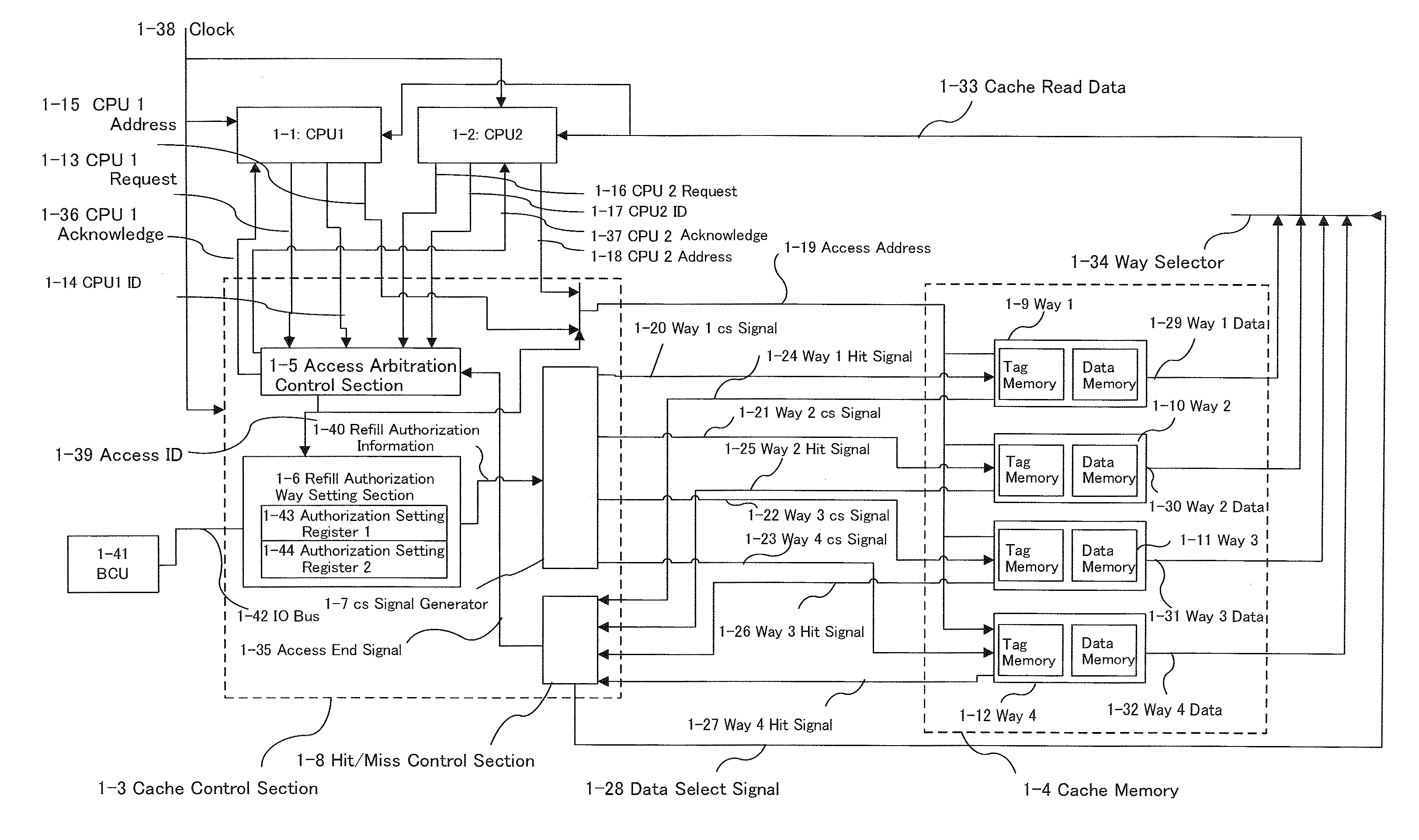
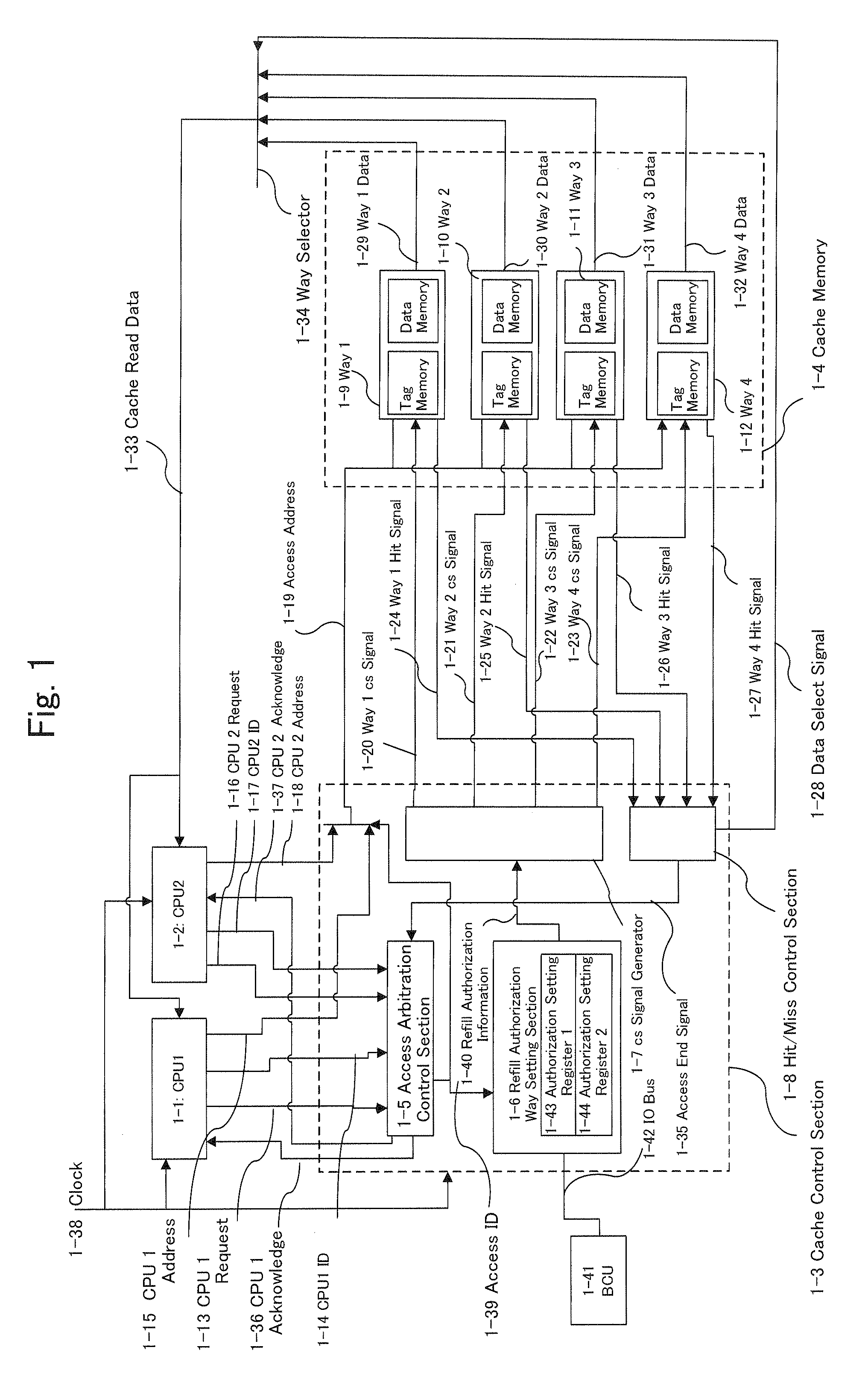
[0086]FIG. 1 illustrates a system configuration diagram of a cache memory control device in Embodiment 1. In FIG. 1, functional parts required for a cache hit operation at the time of a read access are shown. This system is operated by allowing a CPU 1 (1-1) and a CPU 2 (1-2) to share a cache memory (1-4) via a cache control section (1-3).

[0087]In the cache control section (1-3), the reference numeral (1-5) denotes an access arbitration control section, the reference numeral (1-6) denotes a refill authorization way setting section, the reference numeral (1-7) denotes a CS (Chip Select) signal generator, and the reference numeral (1-8) denotes a hit / miss control section. The reference numeral (1-43) denotes an authorization setting register 1, and the reference numeral (1-44) denotes an authorization setting register 2. The reference numeral (1-41) denotes a BCU (Bus Control Unit) functioning as a bus control section, and the reference numeral (1-42) denotes an IO (Input / Output) bus....

embodiment 2

[0130]FIG. 5 illustrates a flow chart of a cache access in Embodiment 2 of the present invention.

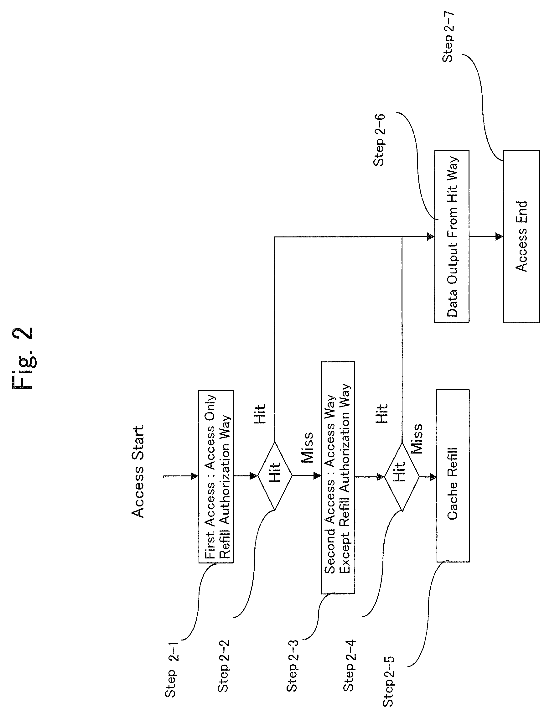
[0131]In Embodiment 2, only the number of the ways accessed during a second access differs from that in Embodiment 1, and the steps from the access start to a first access (i.e., Steps 2-1 and 2-2) and the steps subsequent to the second access (i.e., Steps 2-4, 2-5, 2-6 and 2-7) are similar to those in Embodiment 1.

[0132]In Embodiment 2, all the ways are accessed in the second access (Step 3-1).

[0133]FIG. 6 illustrates a timing diagram in Embodiment 2. The diagram shows the timing in the case where a hit has occurred in the way that is not allocated.

[0134]It should be noted that if a hit occurs in the allocated way, the access timing is exactly similar to that in Embodiment 1 (FIG. 3).

[0135]The operation of Cycle 6-1 is similar to that of Cycle 3-1 in FIG. 3.

[0136]In Cycle 6-1, since a hit does not occur in the way 1 and the way 2 which have been accessed, the way 1 hit signal (1-24) and...

embodiment 3

[0142]FIG. 7 illustrates a system configuration diagram of a cache memory control device in Embodiment 3. In FIG. 7, functional parts required for a cache hit operation at the time of a read access are shown.

[0143]A CPU (7-1) in this system is a CPU that executes a plurality of programs while switching information on internal resource such as a program counter by the hour, or a CPU that performs parallel execution of a plurality of programs by one CPU (multithread). Herein, the CPU (7-1) of the present embodiment is a CPU that performs a normal multithread operation and does not allow a thread to be switched during execution of a memory access.

[0144]The reference numeral (7-2) denotes an access control section, the reference numeral (7-3) denotes a CPU address, the reference numeral (7-4) denotes a CPU request, the reference numeral (7-5) denotes a CPU acknowledge, and the reference numeral (7-6) denotes a process ID. The reference numeral (7-7) denotes an authorization setting regi...


PUM


Abstract

An object of the present invention is to reduce power consumption accompanying a cache hit/miss determination. To achieve this object, when accessing a cache memory provided with a means for setting whether a cache refill to each way in the cache memory is allowed for each CPU or each thread, first, a first cache hit/miss determination is performed only on the way for which a refill is set to be allowed (Steps 2-1 and 2-2), and if the first cache hit/miss determination results in a cache hit, the access is ended (Step 2-6). In the case of a cache miss, the way for which a refill is not set to be allowed is accessed (Step 2-3), or a second hit/miss determination is performed by accessing all the ways (Step 2-4).

Description

FIELD OF THE INVENTION[0001]The present invention relates to a cache memory control method and a cache memory control device for a microprocessor provided with a cache memory.BACKGROUND ART[0002]A microprocessor is provided with a cache memory in order to hide an execution penalty for an access to an external memory. Furthermore, in a recent system provided with a microprocessor, in order to improve program execution performance, a multiprocessor system provided with a plurality of processor cores, and / or a processor capable of multithread processing for efficiently executing a plurality of programs with one processor are / is now being employed.[0003]In a multiprocessor and / or a multithreading processor, a memory for executing a plurality of programs is often used by sharing a single memory space. Also in the case of the above-mentioned cache memory, a cache memory is not provided individually for each processor and / or each thread, but a single cache memory or cache memory system is ...

Claims


Application Information

Patent Timeline
IPC IPC(8): G06F12/08G06F12/00
CPCG06F12/084G06F12/0864G06F12/121Y02B60/1225G06F12/128G06F2212/1028G06F2212/6082G06F12/126Y02D10/00
Inventor KANEKO, KEISUKE
Owner BEIJING ESWIN COMPUTING TECH CO LTD
Why Eureka
Try Eureka