Reinforced, regeneratively cooled uni-body rocket engine

a rocket engine and regenerative cooling technology, applied in the field of rocket engines, can solve the problems of increasing the mass of the launcher, liquid oxygen, and significantly increasing the mass of the spaceship

Inactive Publication Date: 2009-09-24
OEHRLEIN ROBERT
View PDF13 Cites 17 Cited by
  • Summary
  • Abstract
  • Description
  • Claims
  • Application Information

AI Technical Summary

Benefits of technology

[0022]The rocket engine according to the present invention uses outside air at altitudes up to about 40,000 feet, then blends on-board oxidizer with the outside air up to about 100,000 feet, and then uses on-board oxidizer alone, thus enabling use of a single type of engine operable at all altitudes, rather than requiring use of a first engine type that uses outside air at lower altitudes and a second engine type that uses on-board oxidizer at higher altitudes.

Problems solved by technology

In spite of the presence of oxygen at low altitudes, conventional space ships, regardless of the type of propellant they burn, carry the required oxygen on-board, adding significantly to the mass of the spaceship.
Liquid oxygen requires thermal insulation and increases the mass of the launcher.
Because of the low temperatures of cryogenic propellants they require thermal insulation and are difficult to store over long periods of time.
They also require a storage volume many times greater than other fuels, increasing the mass of the launcher.
Further, conventional space ships do not provide any means for propulsion upon return to earth, when all the fuel is used up.
When the shower of sparks touches the fuel-oxidizer mixture, there is a sudden all-over ignition.
This is called a hard start and is dangerous and stressful on the equipment.
Conventional rocket engines are typically made of metal, with multiple pieces welded together to form the combustion chamber, throat, and exhaust nozzle or bell, leading to manufacturing complexities and increased cost, with potential failure points.
The use of two extra engines for take off and landing adds significantly to the mass of the space plane.

Method used


Image

  • Reinforced, regeneratively cooled uni-body rocket engine
  • Reinforced, regeneratively cooled uni-body rocket engine
  • Reinforced, regeneratively cooled uni-body rocket engine

Examples


Embodiment Construction

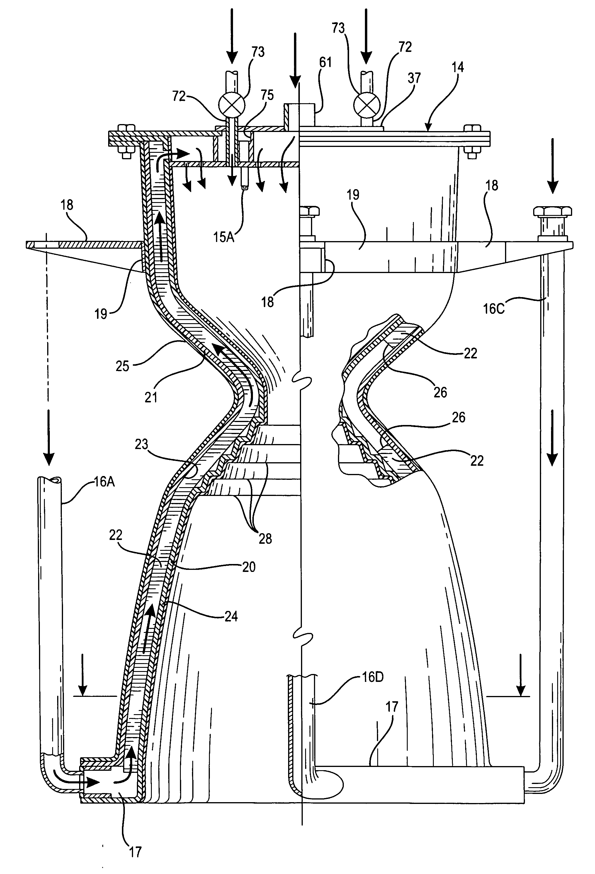
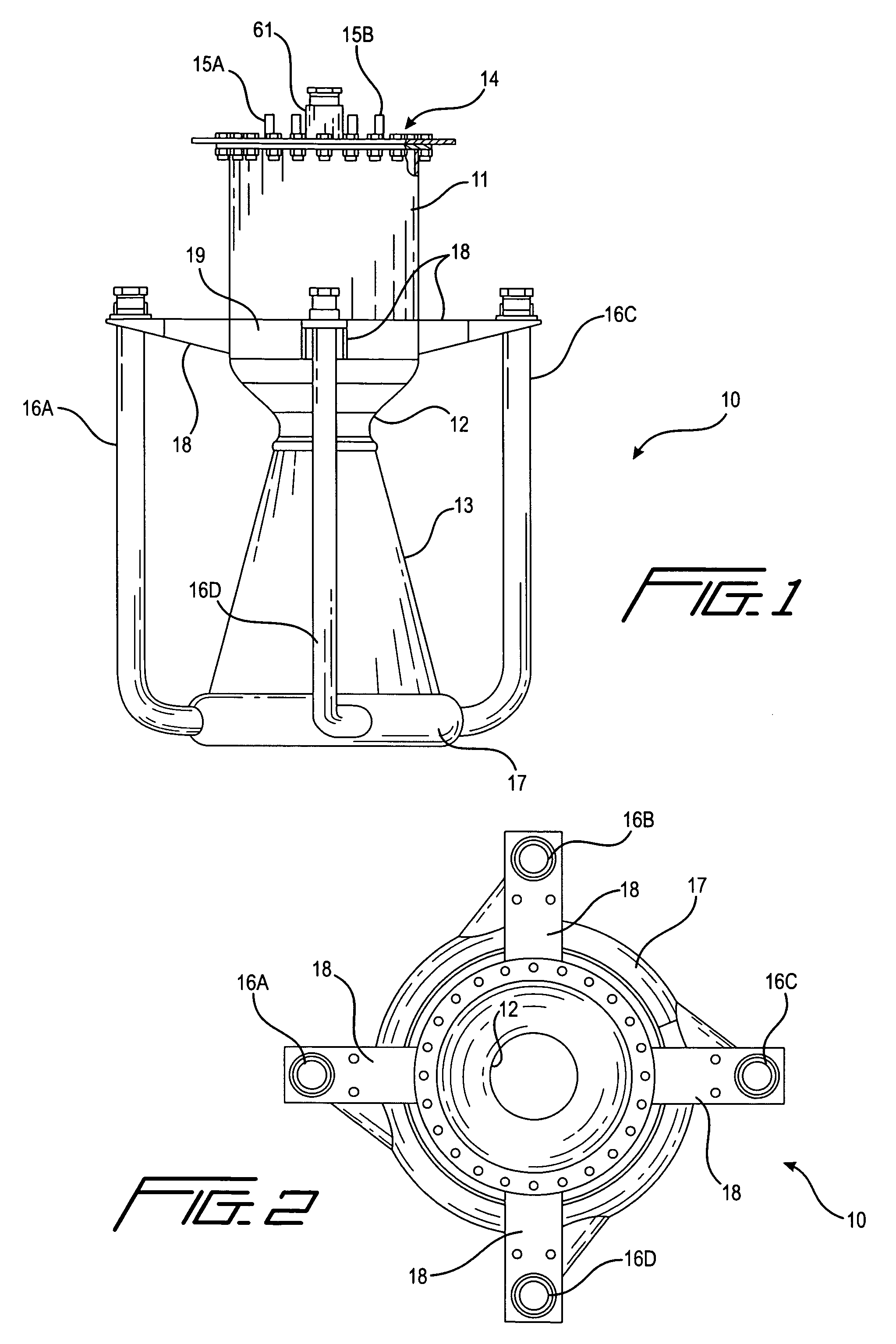
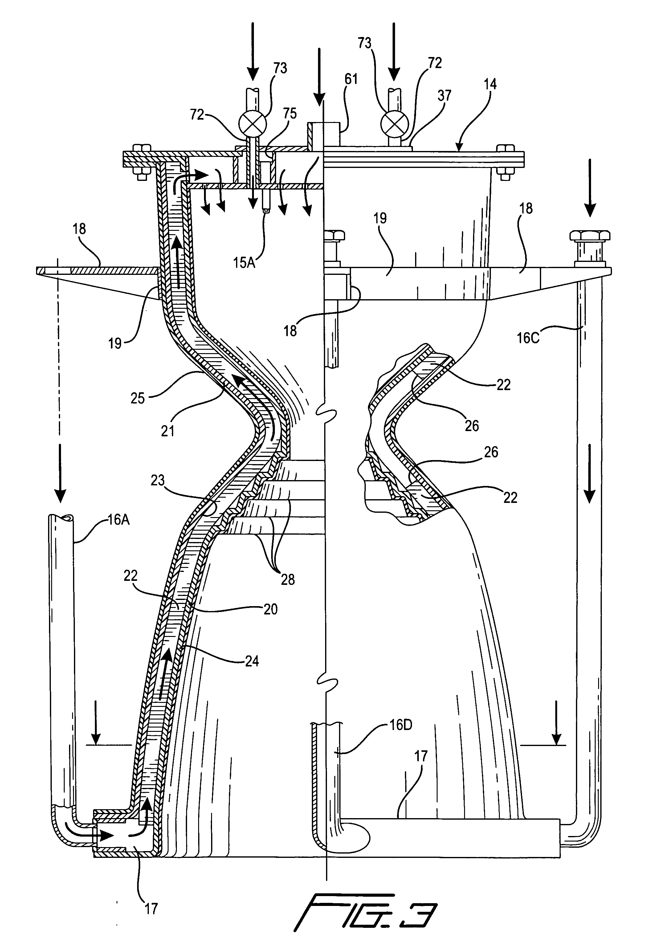
[0062]A first embodiment of rocket engine according to the invention is shown in FIGS. 1-21 and 28. As seen in FIG. 1, the engine 10 comprises a combustion chamber 11 of substantially cylindrical shape, a reduced diameter throat 12, and an outwardly flared exhaust bell or nozzle 13, forming a rocket engine body of substantially conventional shape but incorporating unique features as described hereinafter. A fuel plate assembly 14 is mounted to the upper end of the combustion chamber for supplying fuel and oxidizer to the combustion chamber, and igniters 15A and 15B extend through the fuel plate assembly and into the combustion chamber for igniting the fuel and oxidizer mixture. Four oxidizer tubes 16A, 16B, 16C and 16D are provided in this embodiment, extending longitudinally of the engine and connected tangentially at their lower ends to an oxidizer ring 17 on the bottom end of the exhaust bell, and connected at their upper ends to mounting brackets 18 that are in turn secured to a...


PUM


Abstract

A rocket engine having a combustion chamber, a throat, and an exhaust bell is made with spaced apart inner and outer skins each unitarily formed in one piece of carbon fiber fabric. Longitudinal ribs in the space between the skins reinforce the engine and divide the space into a plurality of flow channels. An oxidizer ring at the bottom of the exhaust bell is in fluid flow communication with the flow channels, and one or more oxidizer tubes are connected tangentially at one end to the ring to supply oxidizer to the ring and thence to the flow channels. The oxidizer tubes are connected at their other end to the engine above the throat, further reinforcing the engine. An igniter is in the combustion chamber, and ignition fuel ports are directed toward the igniter to provide a soft start ignition.

Description

TECHNICAL FIELD[0001]This invention relates generally to rocket engines, and more particularly to a reinforced, regeneratively cooled, uni-body rocket engine with a soft-start ignition.BACKGROUND ART[0002]Conventional rockets take off vertically and use a propellant that is a chemical mixture of fuel and oxidizer burned to produce thrust. The single heaviest item carried by a spaceship is the propellant, of which the oxidizer comprises the majority.[0003]The greatest rate of oxygen consumption for a rocket engine is relatively close to the ground, where atmospheric air up to about 40,000 feet contains a relatively large amount of oxygen. In spite of the presence of oxygen at low altitudes, conventional space ships, regardless of the type of propellant they burn, carry the required oxygen on-board, adding significantly to the mass of the spaceship.[0004]In liquid propellant rockets the fuel and oxidizer are stored in separate tanks and fed through a system of pipes, valves, and pumps...

Claims


Application Information

Patent Timeline
Patent Type & Authority Applications(United States)
IPC IPC(8): F02K9/00
CPCF02K7/18F02K9/00F05D2300/603F02K9/972F02K9/64
Inventor OEHRLEIN, ROBERT
Owner OEHRLEIN ROBERT
Why Eureka
Try Eureka