Exhaust gas switching valve

a technology of exhaust gas switching valve and switching valve, which is applied in the direction of mechanical equipment, machines/engines, light and heating apparatus, etc., can solve the problems of valve clearance not being easily made smaller, and cooling efficiency of egr gas, so as to restrict the avoid the effect of deterioration of emission reducing performan

Inactive Publication Date: 2009-09-24
DENSO CORP
View PDF2 Cites 28 Cited by
  • Summary
  • Abstract
  • Description
  • Claims
  • Application Information

AI Technical Summary

Benefits of technology

[0011]The present invention is made in view of the above matters, and it is an object of the present invention to provide an exhaust gas switching valve capable of restricting a hot EGR gas leakage which causes an increment in temperature of exhaust gas, thereby restricting a deterioration of an emission reducing performance.
[0012]According to the present invention, an exhaust gas switching valve includes: a housing having four gas ports which respectively communicate to an exhaust passage, an intake passage, an inlet of an exhaust gas cooler, and an outlet of the exhaust gas cooler; and a valve rotatably accommodated in the housing to switch a communicating condition of the ports. A partition wall partitions the cooler inlet port and the cooler outlet port. The partition wall extends from the connecting portion of the housing and the exhaust gas cooler to a vicinity of a valve shaft. Therefore, an increase in temperature of the exhaust gas flowing out from the exhaust gas outlet port at cooler mode and an increase in temperature of the cooled exhausted gas passed through the exhaust gas cooler can be restricted, so that deterioration of the emission reducing performance can be avoided.

Problems solved by technology

Thus, the cooling efficiency of the EGR gas is decreased and the emission reducing performance is deteriorated.
Although it is considerable that the valve clearances are made smaller to restrict a leakage of the hot EGR gas, the valve clearances are not easily made smaller due to tolerances of parts and differences in linear expansion coefficient.

Method used


Image

  • Exhaust gas switching valve
  • Exhaust gas switching valve
  • Exhaust gas switching valve

Examples


first embodiment

[Operation of First Embodiment]

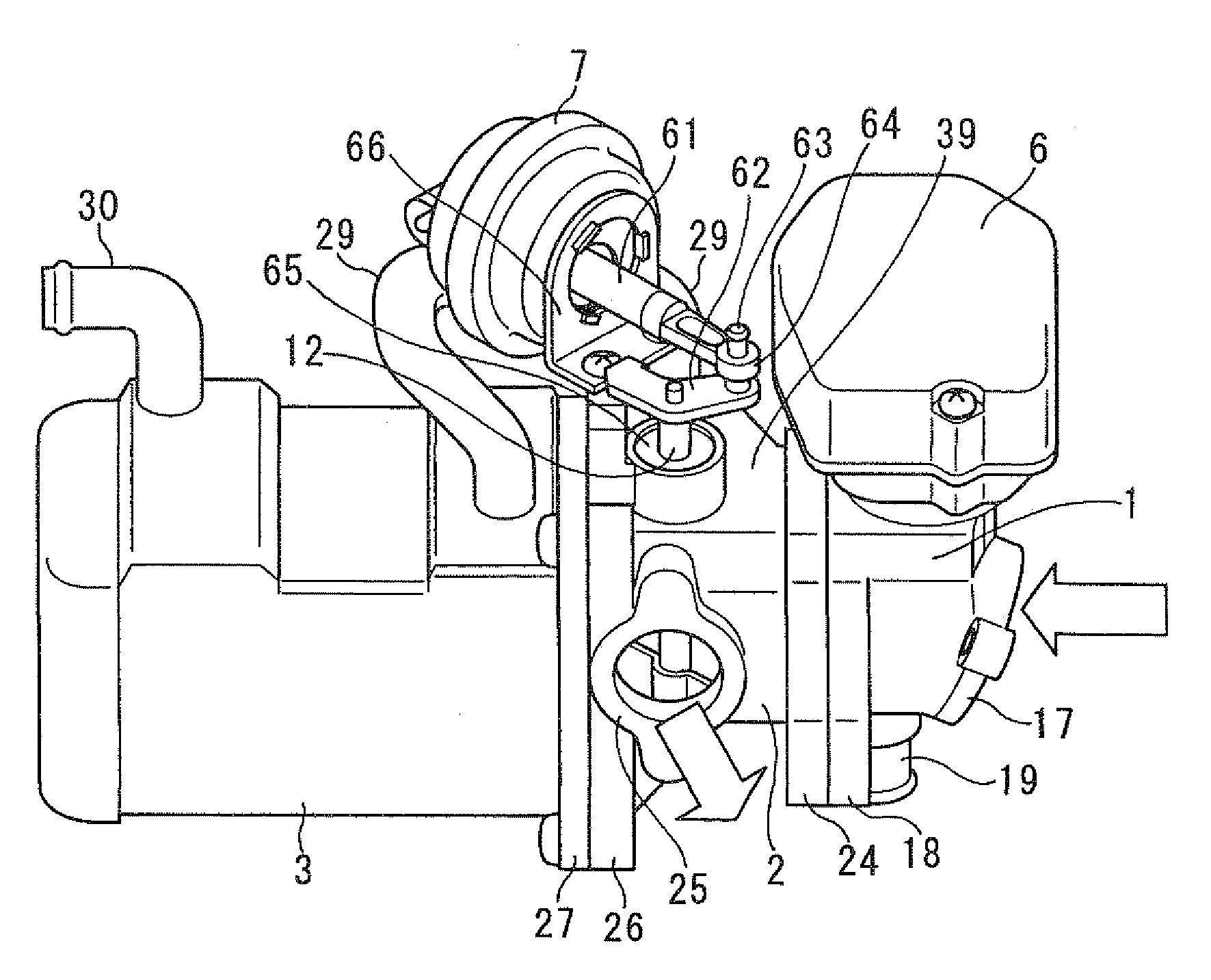
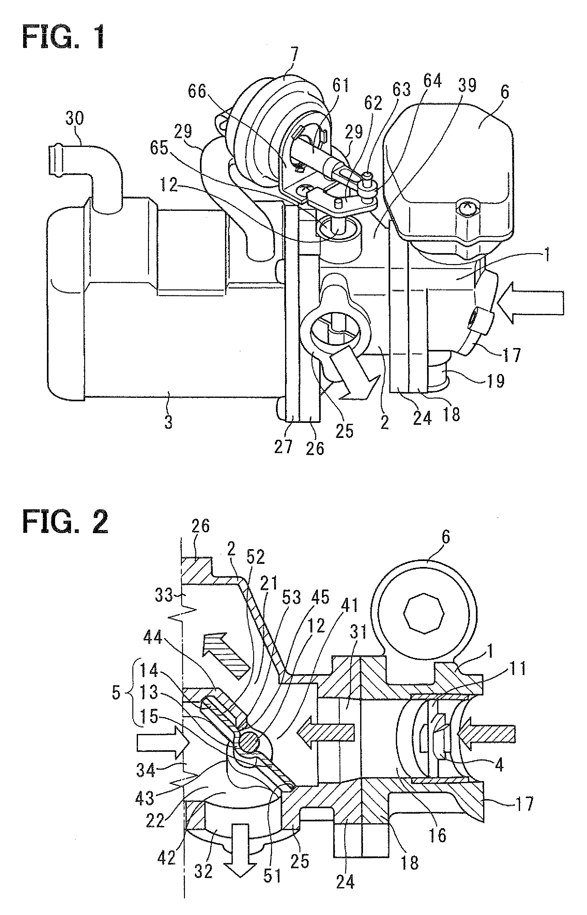
[0047]Referring to FIGS. 1 to 3, an operation of the EGR cooler module will be briefly described hereinafter.

[0048]When the ignition switch is turned on to start the engine, the ECU feedback controls electric power supplied to the electric motor of the first actuator 6 in such a manner that the actual EGR quantity agrees with a target EGR quantity. When the electric motor is energized, the driving force of the motor is transmitted to the shaft so that the first control valve body 4 is drove from a full closed position to an opened position.

[0049]The first control valve body 4 is positioned at a specified position corresponding to a target control value. A part of the exhaust gas discharged from the combustion chamber of the engine recirculated from the exhaust pipe to the intake pipe through the first EGR gas passage 21, the EGR cooler 3, the second EGR gas passage 22.

[0050]When the engine load is middle or high, the four-way butterfly valve 5 is broug...

second embodiment

[0059]FIG. 5 shows a four-way butterfly valve 5 according to the second embodiment. The four-way butterfly valve 5 is rotatably accommodated in a valve chamber of the housing 2. The second actuator 7 rotates the four-way butterfly valve 5 through the shaft 12.

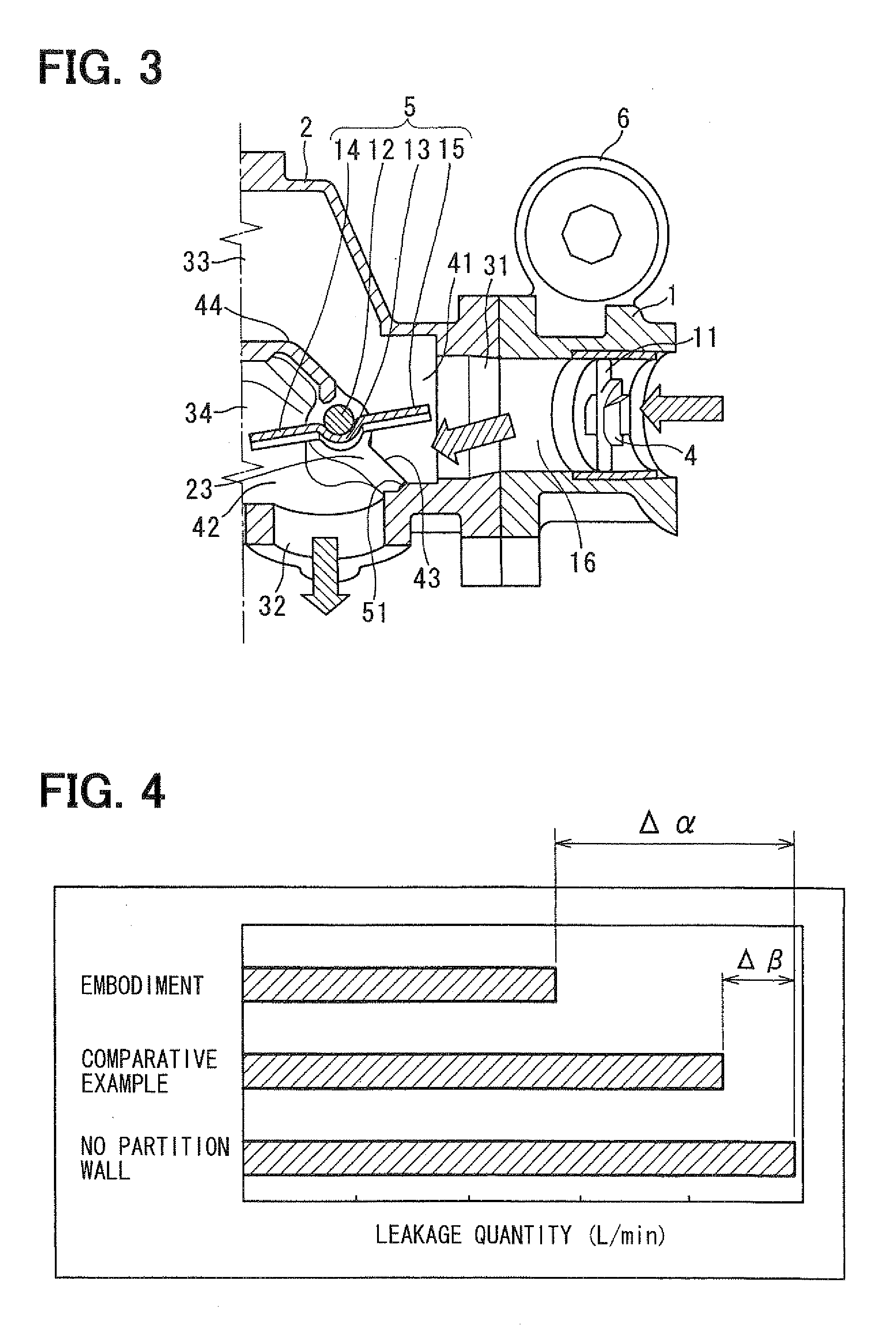
[0060]The partition wall 44 has a protrusion 45 which protrudes toward the butterfly valve 5. The protrusion 45 can be brought into contact with the contacting portion 53 provided on the overlap portion 52 of the first valve plate 14. The protrusion 45 has a flat surface on which the contacting portion 53 is brought into contact. The first valve plate 14, the overlap portion 52, and the contacting portion 53 have flat surfaces confronting to the partition wall 44. The contacting position of the protrusion 45 and the contacting portion 53 is formed at a vicinity of the shaft 12. The protrusion 45 and the contacting portion 53 can be contacted with each other by surface contact at the cooled mode. The protrusion 45 has a function...


PUM


Abstract

A partition wall partitioning a cooler inlet port and a cooler outlet port extends from a cooler connecting surface of a connecting portion to a vicinity of a shaft supporting a four-way butterfly valve. An EGR gas leakage around a first valve plate can be restricted. Thus, an increase in temperature of EGR gas flowing through an EGR gas outlet port can be restricted at a cooled mode. A deterioration of emission reducing performance can be avoided.

Description

CROSS-REFERENCE TO RELATED APPLICATION[0001]This application is based on Japanese Patent Application No. 2008-74111 filed on Mar. 21, 2008, the disclosure of which is incorporated herein by reference.FIELD OF THE INVENTION[0002]The present invention relates to an exhaust gas switching valve provided in an exhaust gas recirculation system. The exhaust gas switching valve switches between a cold mode (cooler mode) in which the exhaust gas flows through an exhaust gas cooler and a hot mode (bypass mode) in which the exhaust gas bypasses the exhaust gas cooler.BACKGROUND OF THE INVENTION[0003]An exhaust gas recirculation system (EGR system) has been well known. The EGR system is provided with an exhaust gas cooler (EGR cooler) cooling the recirculated exhaust gas with engine coolant. A combustion temperature is decreased without deteriorating an output of an internal combustion engine, so that noxious agents, such as NOx, contained in the exhaust gas are reduced.[0004]Further, when the ...

Claims


Application Information

Patent Timeline
Patent Type & Authority Applications(United States)
IPC IPC(8): F01N7/00F01N5/02F02M25/07
CPCF02M25/0729F02M25/0735Y02T10/121F28F27/02F02M25/0737F02M26/32F02M26/26F02M26/30
Inventor KOBAYASHI, TAKASHISHIMANE, OSAMUHASHIMOTO, KOJI
Owner DENSO CORP
Why Eureka
Try Eureka