Two-stage cooling system

a cooling system and two-stage technology, applied in the field of two-stage cooling systems, can solve the problems of affecting the operation of the cooling system, and the safety of the user, so as to reduce the noise, dampen the noise, and dampen the noise

Active Publication Date: 2009-09-24
ILLINOIS TOOL WORKS INC
View PDF9 Cites 11 Cited by
  • Summary
  • Abstract
  • Description
  • Claims
  • Application Information

AI Technical Summary

Benefits of technology

[0011]A first thermostat may be operatively attached to the first vortex tube and extend outwardly from the cabinet. Likewise, a second thermostat may be operatively attached to the second vortex tube and extend outwardly from the cabinet. The first and second thermostats may each be configured to be positioned within the interior of the enclosure. Because each of the vortex cooling devices inside the cabinet is controlled by a separate mechanical thermostat, they can be adjusted so that only one cooler operates when the heat load (temperature in the enclosure) is low; and then, if and when the heat load rises, the second vortex cooling device is activated. This allows for reduced compressed air consumption during periods of low heat load.
[0013]One or more one-way check valves may be operatively attached to the second hot pipe to prevent backflow of hot exhaust from the first hot pipe into the second hot pipe.
[0014]A dampening sleeve may be secured around at least a portion of each of the first and second hot pipes. The dampening sleeves may be formed of rubber and act to absorb, dampen, or otherwise reduce noise produced by the respective vortex tube.
[0015]The cabinet may include a base integrally formed with a rear wall and lateral walls. An upper wall may be integrally formed with the rear wall and the lateral walls, together defining the venting chamber. A cover may be placed over the venting chamber, and at least one dampening sheet may line at least a portion of the base, the rear wall, the lateral walls, and / or the upper wall. The dampening sheet is configured to dampen noise produced by the first and second vortex tubes. Additionally, flexible dampening rods may be disposed within the venting chamber to further dampen noise produced by the vortex tubes.
[0018]One or more bleed air holes may be configured to be in fluid communication with the interior of the enclosure and a source of air. The bleed air hole is operable to allow air to pass into the enclosure to maintain a pressure differential between the interior of the enclosure and an outside environment. The pressure differential prevents debris from infiltrating into the enclosure even when the vortex tube is deactivated.

Problems solved by technology

Typically, the enclosures house various components that may be adversely affected by temperatures elevated above room or ambient temperature.
In the case of enclosures containing electrical equipment, heat buildup within the enclosures can damage the components and / or cause safety hazards, for example, fires.
Many of these enclosures, particularly those that are substantially or completely sealed, are not easily ventilated.
The systems disclosed in the '768 patent, however, provide a cooling system that produces high noise levels.
In particular, the noise created by the high velocity spinning air within a vortex tube may be objectionable to some.
Such noise may annoy, irritate, or even cause discomfort to, an operator of the enclosure, or those in close proximity to the enclosure.
The mufflers, however, do not substantially reduce the noise levels a significant amount.
The system disclosed in the '513 patent has a single cooling device, which results in a limited cooling capacity of the system.
Because its first stage cooler is a heat exchanger (and not an ‘active’ cooling device), temperatures inside the enclosure used with the system may never be cooled below the ambient temperature conditions.

Method used


Image

  • Two-stage cooling system
  • Two-stage cooling system
  • Two-stage cooling system

Examples


Embodiment Construction

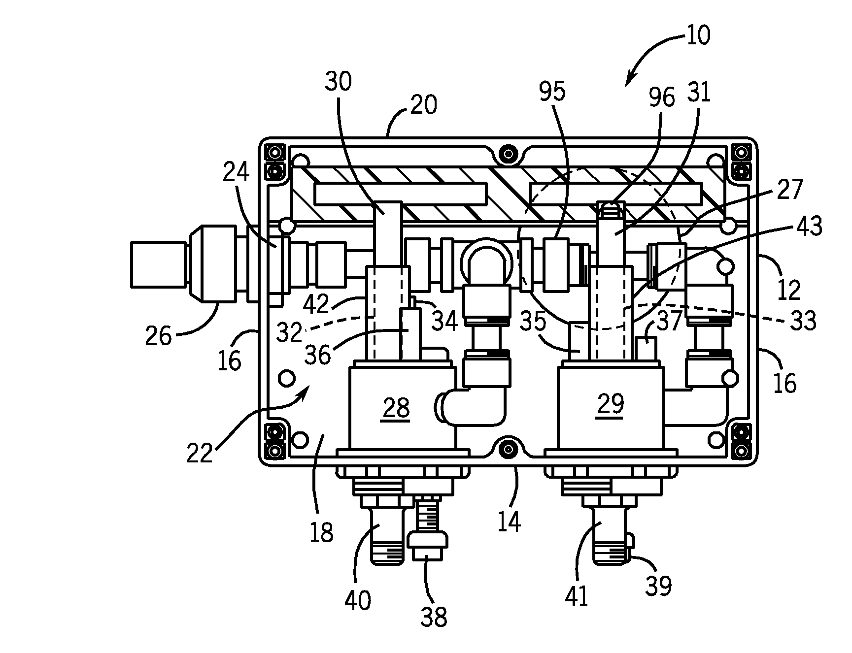
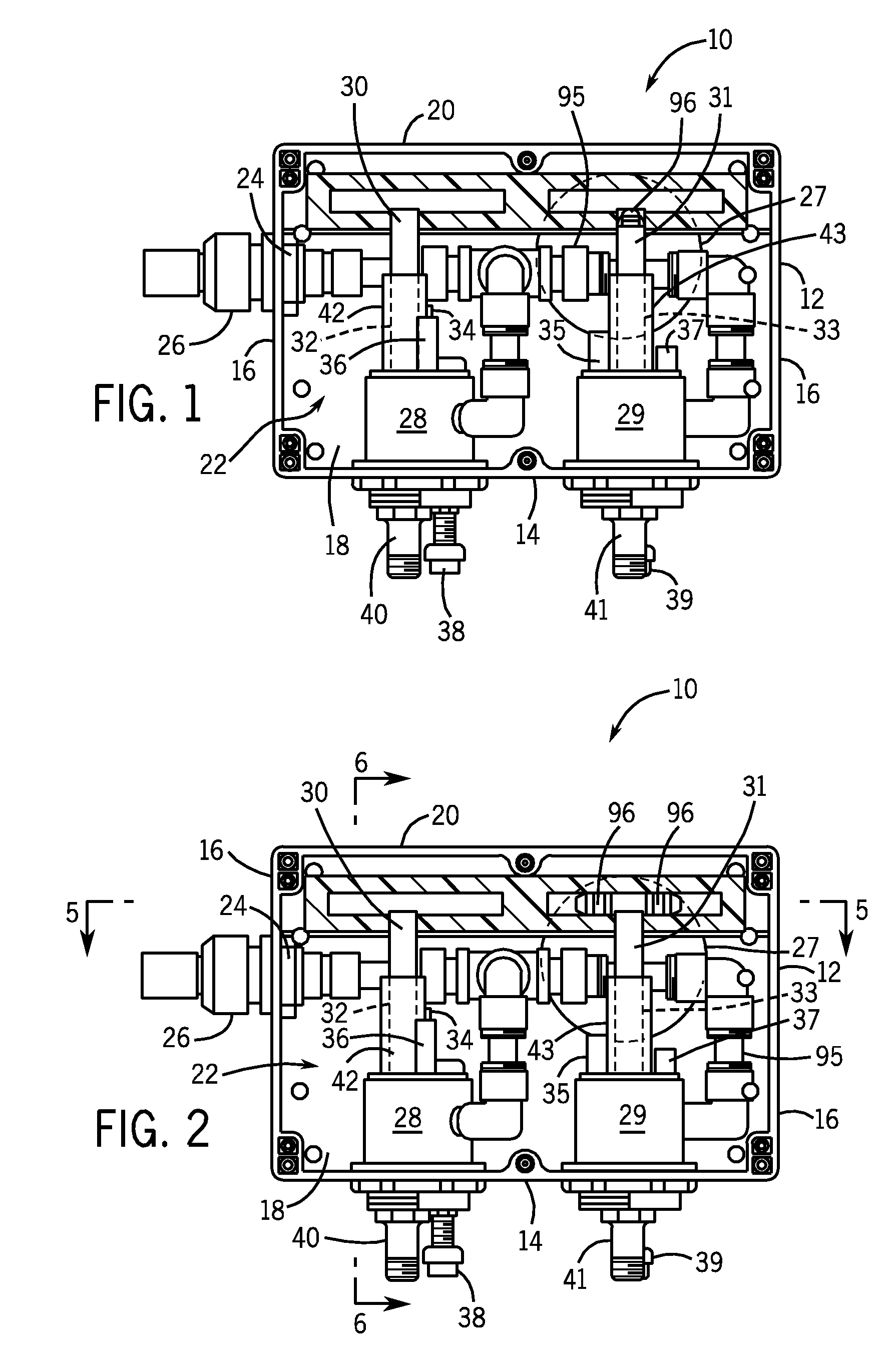
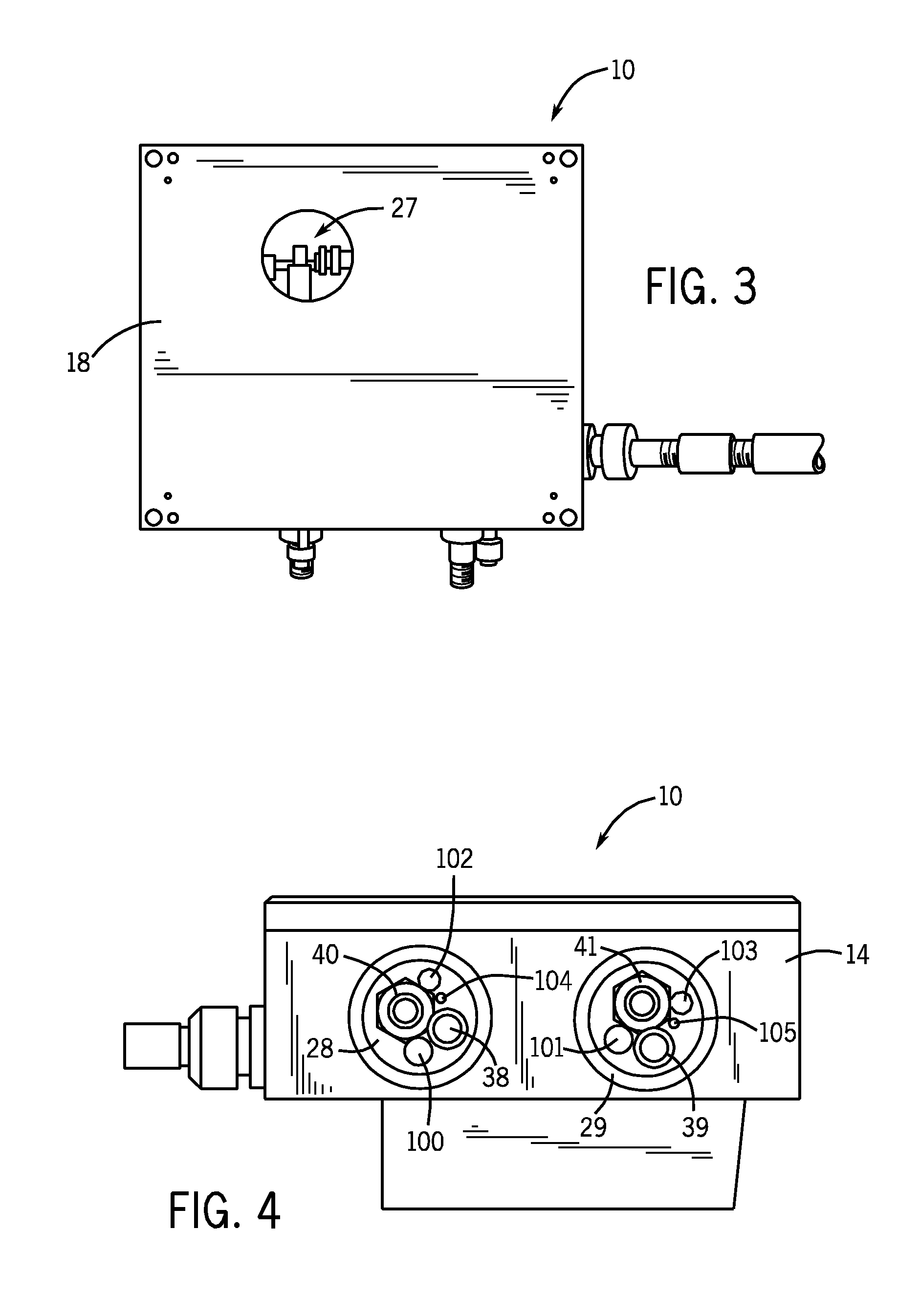
[0036]FIG. 1 illustrates a front perspective interior view of a two-stage cooling system 10 according to an embodiment of the present invention. The cooling system 10 includes a cabinet 12, which may be formed of polycarbonate, that includes a base 14 integrally formed with lateral walls 16, and a rear wall 18. The lateral walls 16 and rear wall 18 are, in turn, integrally formed with an upper wall 20. The base 14, the lateral walls 16, the rear wall 18, and the upper wall 20 define a venting chamber 22 therebetween. A removable front cover (not shown in FIG. 1) is secured to edges of the base 14, lateral walls 16, and upper wall 20 to enclose the venting chamber 22.

[0037]A gas inlet passage 24 is formed through one of the lateral walls 16. The gas inlet passage 24 is configured to receive and retain a gas delivery tube, pipe, duct, or the like 26 of a gas (such as air) compression system (not shown in FIG. 1). The gas inlet passage 24 may securely retain the gas delivery pipe 26 th...


PUM


Abstract

A two-stage cooling system configured to cool an interior of an enclosure includes a cabinet, a first vortex tube secured within the cabinet, and a second vortex tube secured within the cabinet. The cabinet defines a venting chamber. The first and second vortex tubes each include a hot pipe within the venting chamber and a cool gas delivery pipe extending outwardly from the cabinet. The first and second cool gas delivery pipes are configured to deliver cold gas to the interior of the enclosure. A separate thermostat may be operatively attached to each vortex tube and extend outwardly from the cabinet to be positioned within the interior of the enclosure. Additionally, first and second dampening sleeves may be secured around at least a portion of the first and second hot pipes, respectively, such that the dampening sleeves dampen noise produced by the vortex tubes.

Description

RELATED U.S. APPLICATION DATA[0001]The present invention claims the benefit of the filing date under 35 U.S.C. §119(e) of U.S. Provisional Patent Application Ser. No. 61 / 038,528, filed on Mar. 21, 2008, which is hereby incorporated by reference in its entirety.FIELD OF THE INVENTION[0002]The present invention relates generally to a two-stage cooling system configured to cool the interior of an enclosure.BACKGROUND OF THE INVENTION[0003]Various enclosures, whether they are sealed, substantially sealed, or unsealed to their surrounding environment are cooled. Typically, the enclosures house various components that may be adversely affected by temperatures elevated above room or ambient temperature. In the case of enclosures containing electrical equipment, heat buildup within the enclosures can damage the components and / or cause safety hazards, for example, fires. Many of these enclosures, particularly those that are substantially or completely sealed, are not easily ventilated.[0004]...

Claims


Application Information

Patent Timeline
Patent Type & Authority Applications(United States)
IPC IPC(8): F25B9/04
CPCF25B2500/12F25B9/04
Inventor BROERMAN, STEVEN E.
Owner ILLINOIS TOOL WORKS INC
Why Eureka
Try Eureka