Faraday rotator

a rotator and faraday technology, applied in non-linear optics, instruments, optics, etc., can solve the problems of increasing cost, requiring a strong magnetic field, rotating the plane of polarization, etc., and achieves stable faraday rotation angle, low strength, and compact rotator.

Inactive Publication Date: 2009-09-24
SUMITOMO METAL MINING CO LTD
View PDF3 Cites 10 Cited by
  • Summary
  • Abstract
  • Description
  • Claims
  • Application Information

AI Technical Summary

Benefits of technology

[0026]Thus, in virtue of the action of the pair of fourth magnets constituted of an inside magnet and an outside magnet and in which the inside magnet and the outside magnet stand magnetized in the directions of magnetization that are parallel to the optical axis and the directions opposite to each other, the magnetic field applied to the Faraday elements can not easily come

Problems solved by technology

However, the paramagnetic material such as TGG or terbium glass has a small Verdet constant, and its ability to rotate the plane of polarization is so small that it may require a strong magnetic field.
Then, making the paramagnetic material and permanent magnet huge not only leads to an increase in cost, but also, because of a strong leak magnetic field, makes it difficult to assemble the optical isolator and further to incorporate the optical isolator in the device.
In addition, where the paramagnetic material has a long size in the optical-axis direction, the paramagnetic material absorbs light to come to be of high temperature when laser light is transmitted therethrough, an

Method used


Image

  • Faraday rotator
  • Faraday rotator
  • Faraday rotator

Examples


example 1

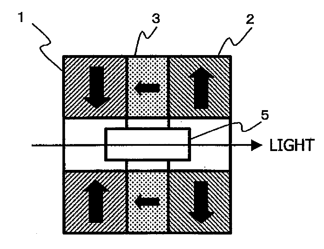
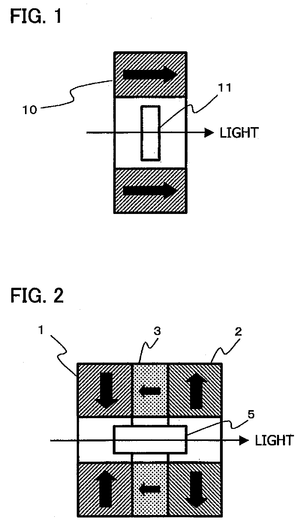
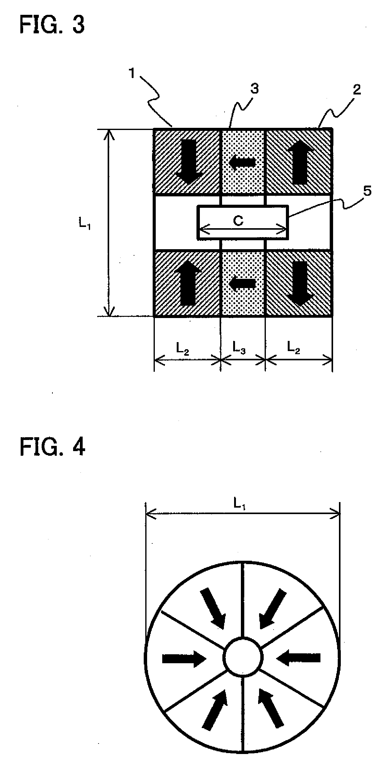
[0045]FIG. 2 is a sectional view showing a Faraday rotator according to Example 1. In FIG. 2, reference numerals 1, 2 and 3 denote a first magnet, a second magnet and a third magnet, respectively, and their directions of magnetization are shown by black arrows. The magnets are each also provided with a hollow space (through-hole) at the center thereof.

[0046]The first magnet 1 stands magnetized in the direction that is perpendicular to the optical axis along which the light is to pass and the direction taken toward the optical axis from the outside. On the other hand, the second magnet 2 stands magnetized in the direction of magnetization that is perpendicular to the optical axis but the direction taken toward the outside from the optical axis as being opposite to that in the first magnet 1. The third magnet 3 is disposed between the first magnet 1 and the second magnet 2 and stands magnetized in the direction of magnetization that is perpendicular to the optical axis and the directi...

example 2

[0060]A Faraday rotator was produced which was so structured that two Faraday rotators which are each the same as the Faraday rotator according to Example 1 were connected in series as shown in FIG. 8 and a pair of fourth magnets 4 constituted of an inside magnet and an outside magnet which stood magnetized in the directions that are each other inversely parallel to the optical-axis direction was inserted between the two Faraday rotators. Here, the inside magnet constituting part of the pair of fourth magnet 4 stood magnetized in the direction of magnetization that is parallel to the optical axis and the direction taken toward the second Faraday rotator on the right side in FIG. 8 from the first Faraday rotator on the left side in FIG. 8. The outside magnet also stood magnetized in the direction of magnetization that is parallel to the optical axis but the direction taken toward the first Faraday rotator on the left side in FIG. 8 from the second Faraday rotator on the right side in...


PUM


Abstract

A Faraday rotator having a magnet member constituted of a first magnet standing magnetized in the direction perpendicular to the optical axis and taken toward the optical axis, a second magnet standing magnetized in the direction perpendicular to the optical axis and taken against the optical axis, and a third magnet disposed between these magnets and standing magnetized in the direction parallel to the optical axis and taken toward the first magnet from the second magnet. A through-hole (hollow spaces) inside which a Faraday element is disposed, is provided through the center of these magnets and, where the length of the first magnet and that of the second magnet in the optical-axis direction are both represented by L2 and the length of the third magnet in the optical-axis direction is represented by L3, the relationship of the following Expression (1) is established:
L2/10≦L3≦L2.   Expression (1)

Description

BACKGROUND OF THE INVENTION[0001]1. Field of the Invention[0002]This invention relates to a magnetic optical device which is used in optical communication systems, laser processing systems and so forth. More particularly, it relates to an improvement in a Faraday rotator used in, e.g., an optical isolator by means of which light emitted from a light source and reflected at an end face of an optical element is prevented from returning to the light source.[0003]2. Description of the Related Art[0004]The Faraday rotator is a functional element consisting basically of a Faraday element and a magnet which applies a magnetic field to this Faraday element to produce Faraday effect. It is used in magnetic optical devices such as an optical isolator which is necessary to intercept light returning to a semiconductor laser to stabilize its lasing; the semiconductor laser being used in optical communication systems, laser processing systems and so forth.[0005]FIG. 1 is a sectional view of a fun...

Claims


Application Information

Patent Timeline
IPC IPC(8): G02F1/09
CPCG02F1/093
Inventor NAKAMURA, NOBUOMAKI, KOICHIRO
Owner SUMITOMO METAL MINING CO LTD
Why Eureka
Try Eureka