

Method for printing a metal paste, metal mask, and bump forming method
- Summary
- Abstract
- Description
- Claims
- Application Information
AI Technical Summary
Benefits of technology
Problems solved by technology
Method used
Image

Examples
first embodiment
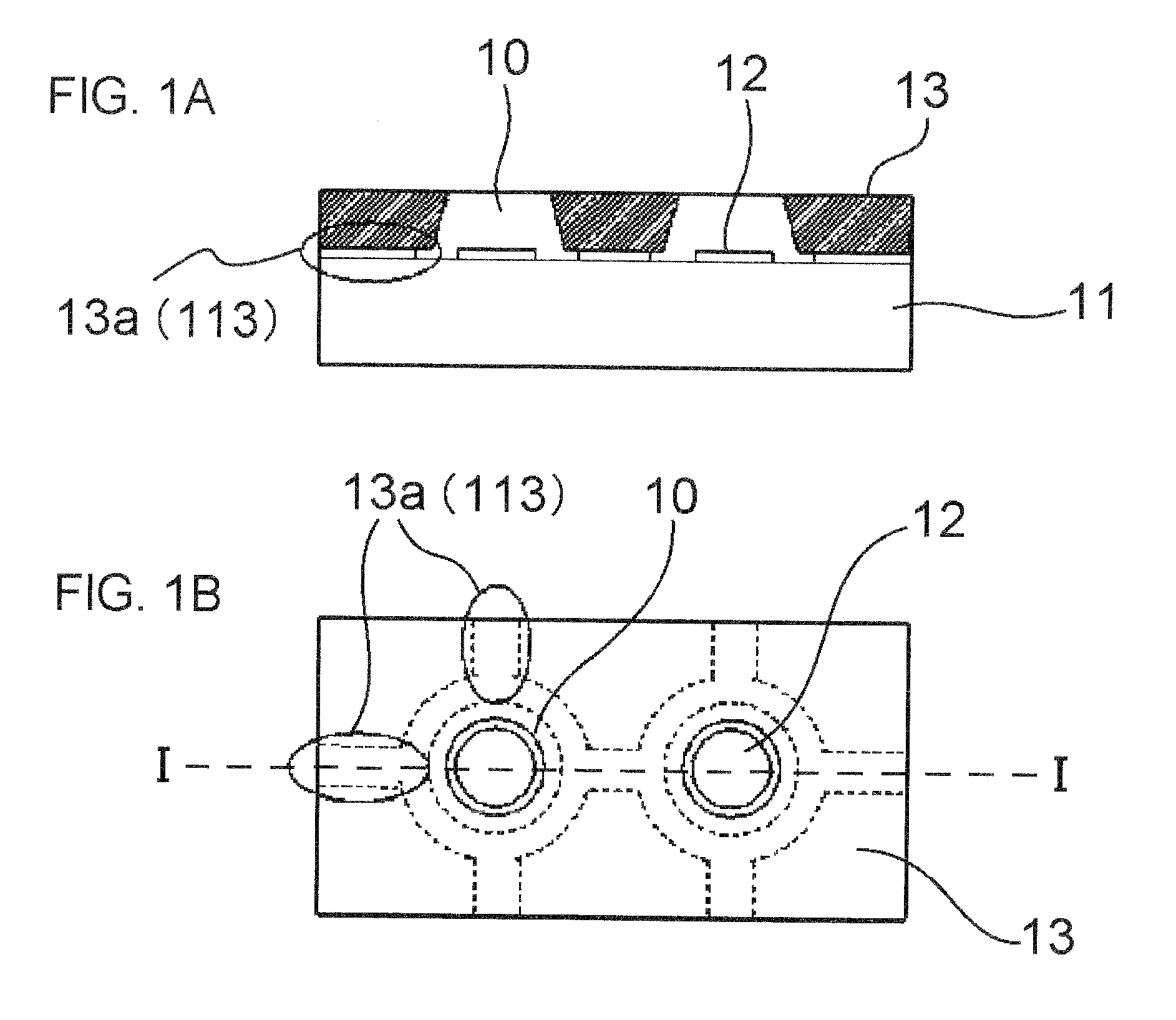
[0027]FIGS. 1A and 1B are a cross-sectional view and a plan view showing a first embodiment of a metal mask according to the present invention. The cross-sectional view shown in FIG. 1A shows a section along an I-I line shown in the plan view in FIG. 1B.
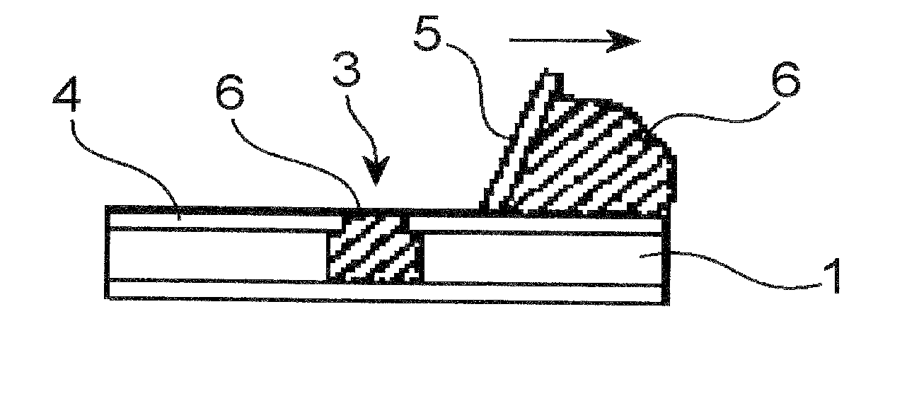
[0028]A metal mask 13 has, on at least one surface of the metal mask 13, a recessed portion 113 which forms a gap portion 13a communicating with a through hole 10 between the metal mask 13 and a substrate 11. The gap portion 13a is configured to guide a flux together with air in the through hole 10.
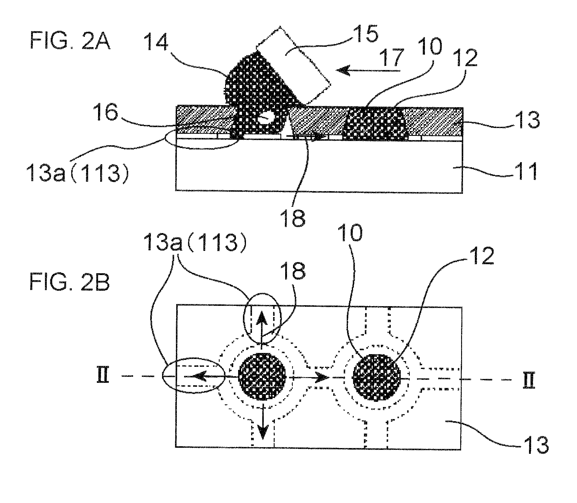
[0029]As shown in FIGS. 2A and 2B, the metal mask 13 is used in a method for printing a metal paste which fills a solder paste 14 containing a flux in the through hole 10 of the metal mask 13 arranged on the substrate 11.
[0030]The substrate 11 is an object to be printed and has an upper surface which is a surface to be printed. An electrode 12 is formed on the substrate 11.
[0031]The through hole 10 is an opening reaching from an upper surf...
second embodiment
[0056]FIG. 5A is a sectional view showing a second embodiment of a metal mask according to the present invention. In the first embodiment, the gap portion 13a is formed to cause the through holes 10 to communicate with each other. In the present embodiment, the through holes 10 do not communicate with each other.
[0057]As shown in FIG. 5A, gap portions 13b are formed for two through holes 10, respectively, and do not communicate with each other. More specifically, the through holes 10 do not communicate with each other. As shown in FIG. 5B, on a lower surface of a metal mask 23, the through hole 10 and a recessed portion 123 (step) extending throughout the circumference of an opening of the through hole 10 are formed. By the recessed portion 123, the gap portion 13b is formed in an interface between the substrate 11 and the metal mask 23.
[0058]The solder paste printing method using the metal mask 23 with the above configuration can be performed by the same manner as described in the ...
third embodiment
[0060]FIGS. 6A and 6B are cross-sectional view and plan view showing a third embodiment of a metal mask according to the present invention. In the second embodiment, the gap portion 13b is formed throughout the circumference of the opening of the through hole 10. In the present embodiment, the gap portion 13c is formed in a part of the circumference of the opening of the through hole 10.
[0061]As shown in FIG. 6A, the gap portion 13c is formed in a part of the circumference of the opening of the through hole 10. As shown in FIG. 6B, the through hole 10 and the recessed portion 133 (step) in a part of the circumference of the opening of the through hole 10 are formed on a lower surface of a metal mask 33. More specifically, the gap portion 13c is formed in a part of the circumference of the through hole 10 on a side (direction indicated an arrow 18) opposite to the arrow 17 indicating a printing direction. The gap portion 13c only has to be a part of the circumference of the through h...
PUM
| Property | Measurement | Unit |
|---|---|---|
| Diameter | aaaaa | aaaaa |
| Height | aaaaa | aaaaa |
| Circumference | aaaaa | aaaaa |
Abstract
Description
Claims
Application Information