Combustor

a combustor and combustor technology, applied in the field of combustor, can solve the problems of adversely limited conditions, liable to undergo pressure fluctuation, and the conventional combustor mentioned above cannot serve satisfactorily as the combustor used in the boiler,

Inactive Publication Date: 2009-09-24
NIPPON CHEM PLANT CONSULTANT
View PDF5 Cites 2 Cited by
  • Summary
  • Abstract
  • Description
  • Claims
  • Application Information

AI Technical Summary

Benefits of technology

[0019]According to the fifth aspect of the invention, a combustion gas flowing out through a through hole from the combustion chamber in the cover member is allowed to pass through the catalyst layer having an oxidation function; hence an unburned combustible which there may remain in the combustion gas after passed to combust through the ceramic combustion tube can completely be burned while passing through the catalyst layer.

Problems solved by technology

Any of the conventional combustors mentioned above cannot serve satisfactorily as a boiler's combustor used for a fuel reforming apparatus in compact fuel cell systems for family use.
The reason is because the combustor used for an apparatus of this type needs to be compact and small in volume of its combustion chamber and requires its surrounding wall surface temperature to be of a 110 to 180°, thus requiring a complete combustion with a reduced NOx concentration, though under very adversely limited conditions for combustion.
In addition, the fuel chamber small in volume means that it is liable to undergo a pressure fluctuation.

Method used


Image

  • Combustor
  • Combustor
  • Combustor

Examples


Embodiment Construction

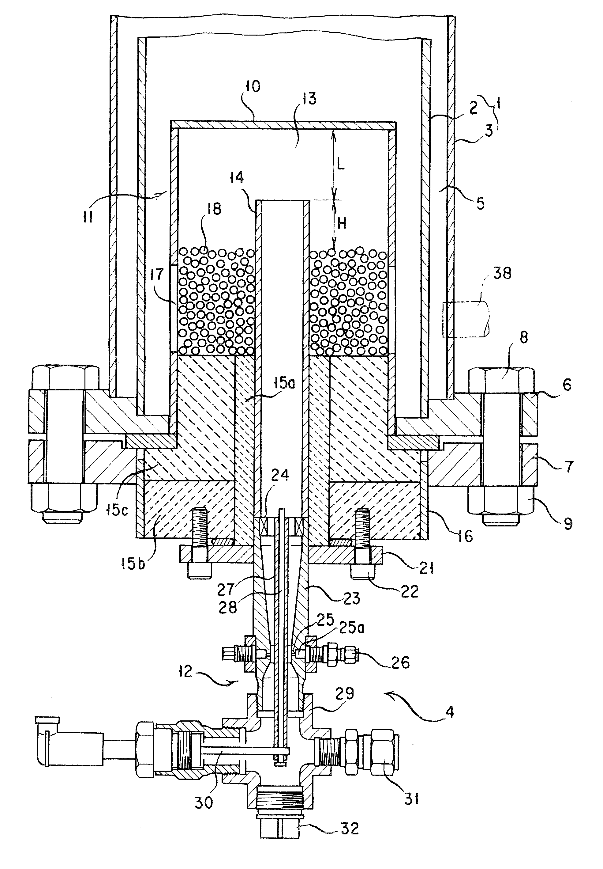
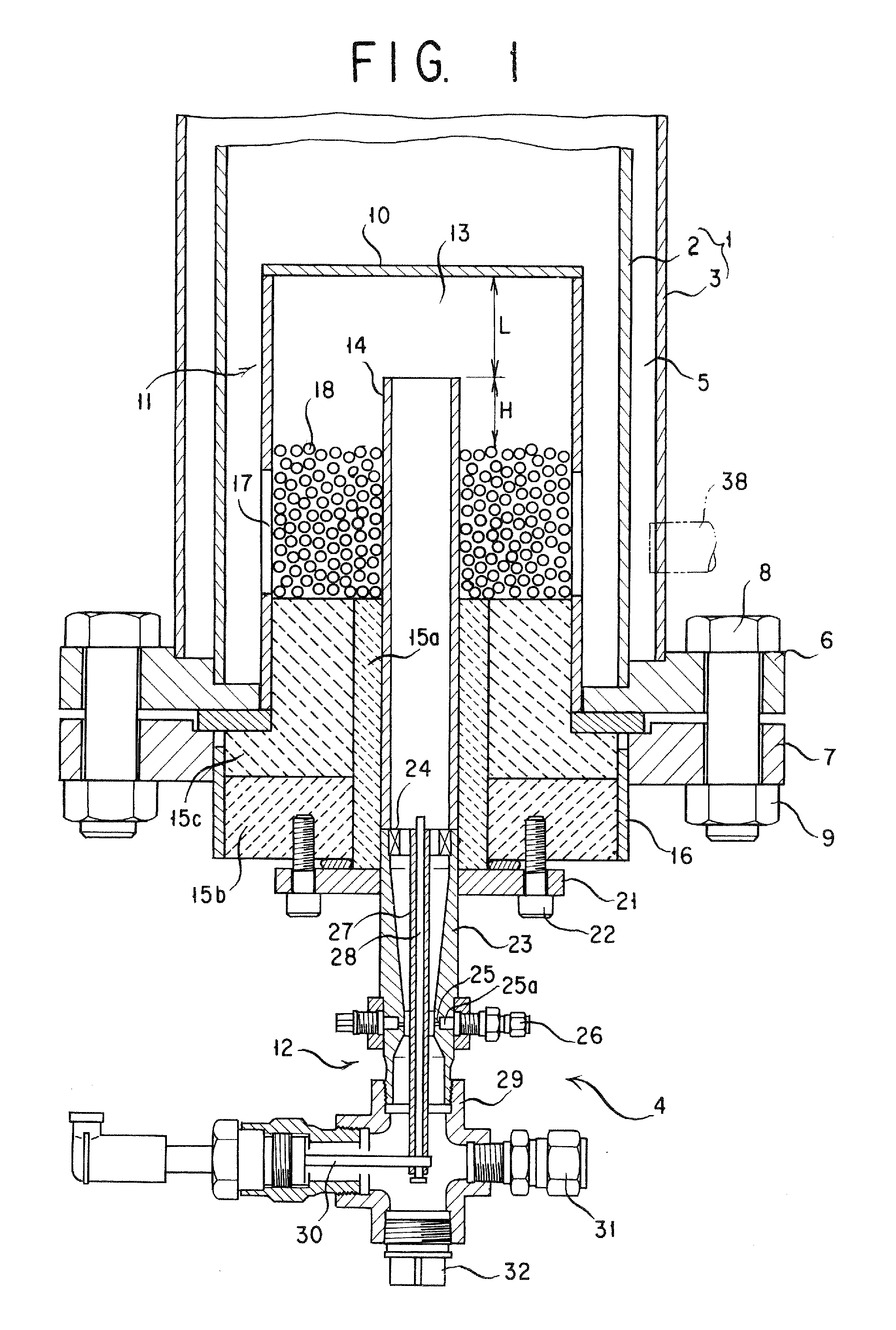
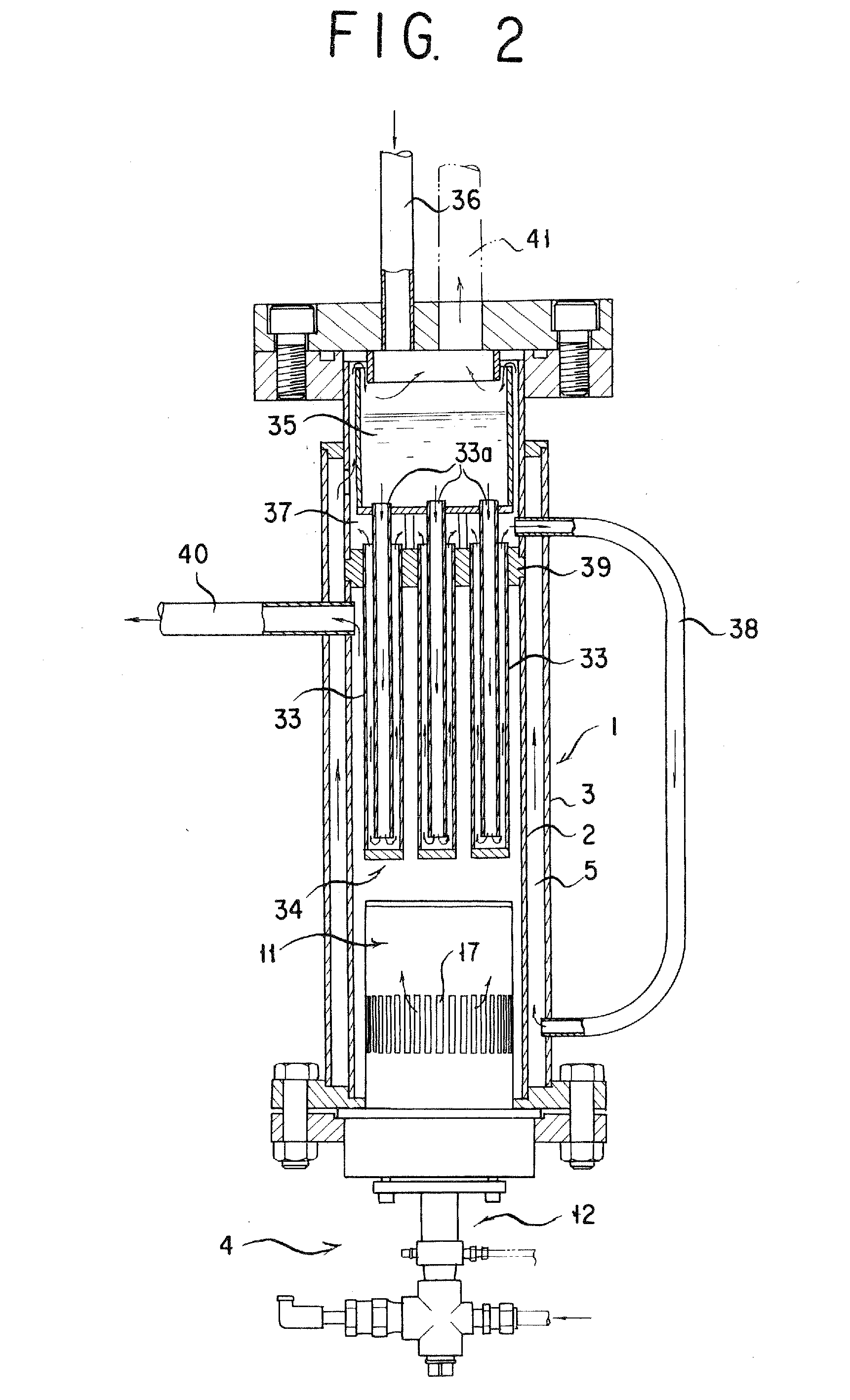
[0024]An explanation is given of a first form of implementation of the present invention with reference to FIGS. 1 and 2. FIG. 1 shows in a cross section the essential parts of a combustor of the present invention, and FIG. 2 shows in a cross section a form of boiler in which the combustor of the invention is used.

[0025]In FIG. 1, a boiler main body 1 comprises an inner cylinder 2 and an outer cylinder 3 coaxially arranged. Mounted at the lower end of the boiler main body 1 is a combustor 4 according to the present invention. A high temperature combustion gas generated by the combustor 4 is supplied into the inner cylinder 2 of the boiler main body 1 along its inner surface to heat the inner surface of the inner cylinder 2 whereby water (evaporating medium) supplied in a heating medium jacket 5 formed between the inner and outer cylinders 2 and 3 coaxially arranged to generate a high temperature steam. A boiler lower flange 6 is coupled integrally with the lower end of the boiler ma...


PUM


Abstract

A combustor is proposed which is compact and eliminates generation of NOx and unburned combustible and is capable of stable combustion.
A combustor is accordingly provided which comprises a combustion section 11, a fuel supply section 12 coupled to the combustion section for supplying a fuel air mixture wherein the fuel supply section comprises a mixer of venturi tube type having a fuel supply port 25 on an inner peripheral surface of a throat part, a combustion air supply port 31 connected to a base end of the mixer of venturi tube type and an igniter made capable of generating a spark at an extremity of the mixer of venturi tube type and the combustion section comprises a frame 16 coupled to the boiler main body and a ceramic combustion tube 14 supported by the frame 16 via heat insulators 15a, 15b and 15c and having one end lying in communication with the extremity of the mixer of venturi tube type in the fuel supply section and the other end projecting into the boiler main body and wherein the ceramic combustion tube is made of a ceramic functioning as an oxidation catalyst.

Description

TECHNICAL FIELD[0001]The present invention relates to a combustor for obtaining a high-temperature gas, e. g., for a fuel reforming apparatus in a compact fuel cell system for family use.BACKGROUND ART[0002]The combustion gas coming from a combustor of this type should desirably be free from pollutants, namely NOx and unburned fuel and be also the least in the amount of residual oxygen by complete combustion.[0003]Conventional combustors of this type are known to include (1) a combustor in which air is mixed with a fuel in a concentration within its explosion mixture limits and a resultant mixed gas of air and fuel is ignited by an igniting means such as electric spark to form a flame, followed by continued combustion of the mixed gas; (2) a combustor in which a preheated mixed gas made by mixing a fuel into preheated air is combusted by means of a combustion catalyst; (3) a combustor in which a heating tube in a primary combustor is always externally heated by an auxiliary combusto...

Claims


Application Information

Patent Timeline
Patent Type & Authority Applications(United States)
IPC IPC(8): F23M3/00
CPCF23C3/002F23D14/02F23C13/06F23C13/00F23C3/00F23D14/18F23D11/40
Inventor MARUKO, SABURONAOI, TOKIOKOMORI, SHINGOMATSUDA, TAKAHIKOYAMAZAKI, YOSHINORI
Owner NIPPON CHEM PLANT CONSULTANT
Why Eureka
Try Eureka