Refrigerant cycle system

a technology of refrigerant cycle and cycle system, which is applied in the direction of domestic cooling apparatus, piston pumps, lighting and heating apparatus, etc., can solve the problems of large current value inputted into electric motors, significantly worsening of air conditioning etc. in passenger compartments, etc., and achieves the effect of avoiding excessive temperature ris

Inactive Publication Date: 2009-10-01
DENSO CORP
View PDF7 Cites 52 Cited by
  • Summary
  • Abstract
  • Description
  • Claims
  • Application Information

AI Technical Summary

Benefits of technology

[0009]The present invention is made in view of the above-mentioned problem. Thus, it is an objective of the present invention to provide a refrigerant cycle system that can perform temperature protection control for avoiding excessive temperature rise of an electric motor of an electric compressor without stopping the electric compressor more than necessary.
[0010]To achieve the objective of the present invention, there is provided a refrigerant cycle system that has an electric compressor, a variable throttle mechanism, a motor temperature detector, a motor protection determiner and a motor protection controller. The electric compressor includes a compression mechanism, which sucks and compresses refrigerant, and an electric motor, which drives the compression mechanism and is cooled by the refrigerant at a suction side of the compression mechanism. The variable throttle mechanism decompresses the refrigerant discharged from the electric compressor. The motor temperature detector detects a temperature of the electric motor. The motor protection determiner determines whether the temperature of the electric motor detected by the motor temperature detector is equal to or higher than a criterion value. The motor protection controller controls the variable throttle mechanism so that an opening degree of the variable throttle mechanism does not decrease when the motor protection determiner determines that the temperature of the electric motor is equal to or higher than the criterion value.

Problems solved by technology

However, if a refrigerant cycle system having the electric compressor is applied to a vehicular air conditioning system, there is a problem that the air conditioning feeling etc. in a passenger compartment becomes worse significantly.
However, when the temperature of the inverter rises, a current value inputted into the electric motor is also large.

Method used


Image

  • Refrigerant cycle system
  • Refrigerant cycle system
  • Refrigerant cycle system

Examples


first embodiment

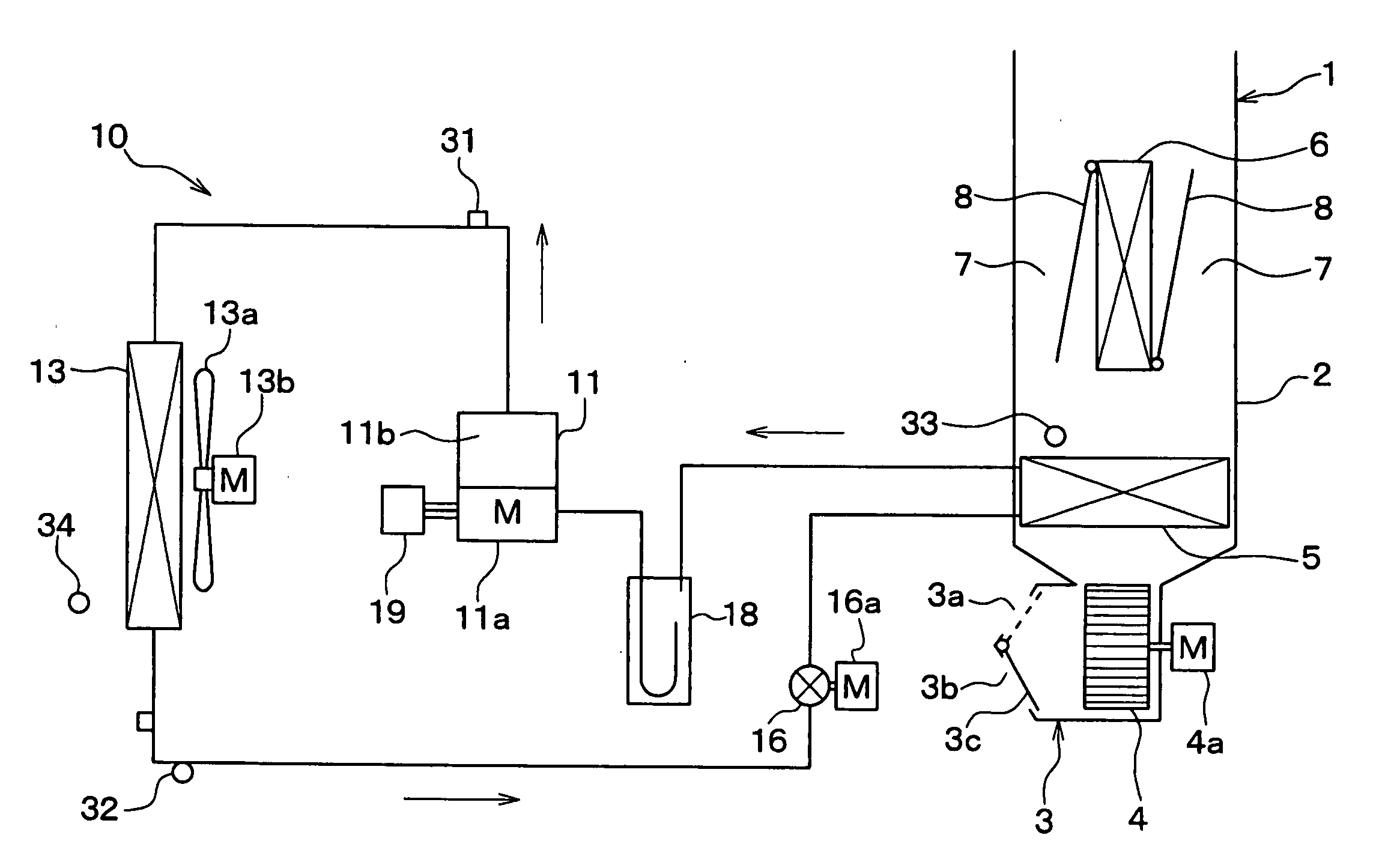
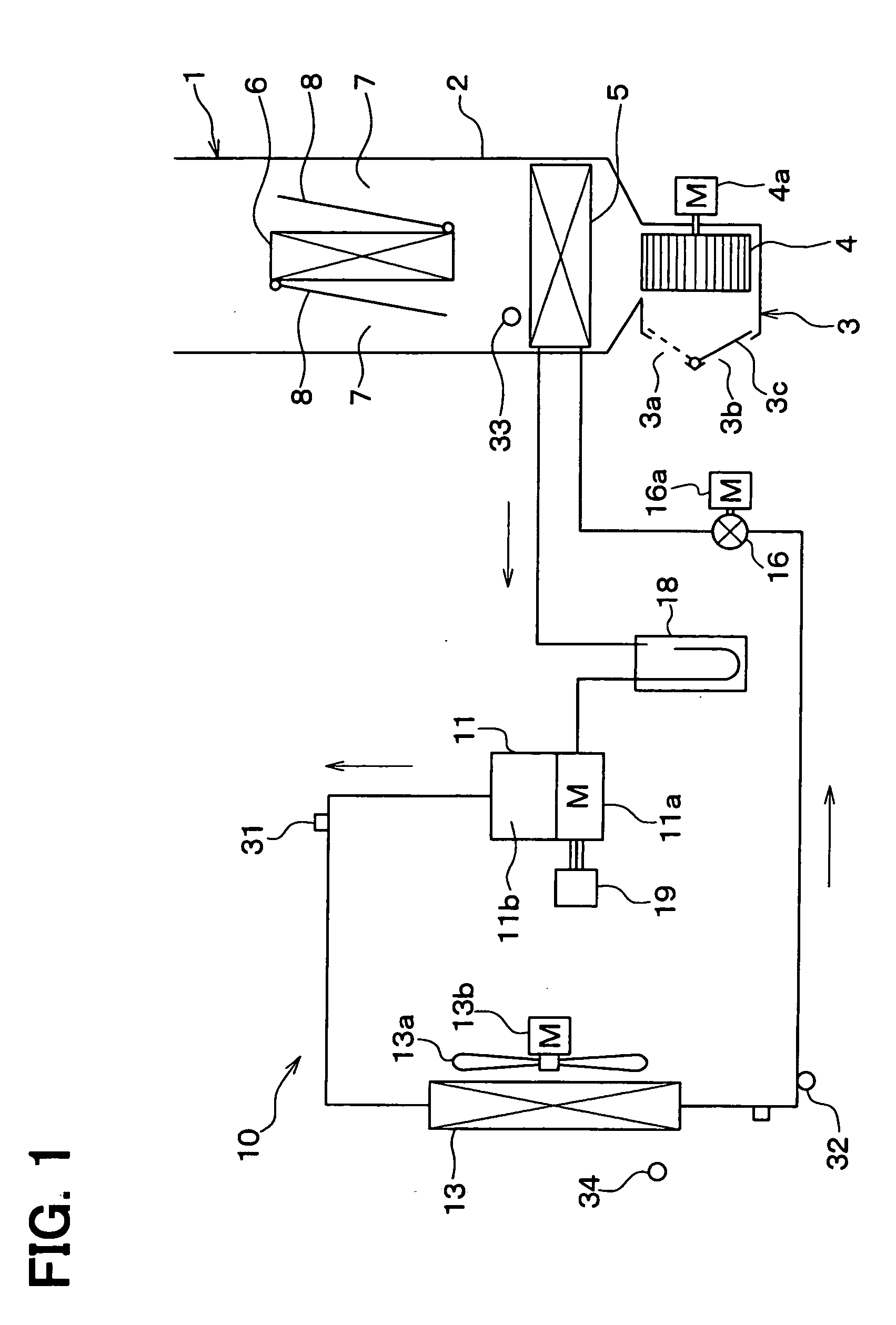
[0019]A first embodiment of the present invention will be described hereafter, referring to FIGS. 1-4. FIG. 1 is a schematic diagram showing an entire construction of a refrigerant cycle system according to the first embodiment, which is applied to a vehicular air conditioning system. As shown in FIG. 1, the vehicular air conditioning system according to the first embodiment has an interior air conditioning unit 1 that is installed inside an instrument panel, which is located at a front-most part of a passenger compartment of a vehicle to form an instrument board etc.

[0020]The interior air conditioning unit 1 has a case member 2 that is made of resin. The case member 2 forms an outer shell of the interior air conditioning unit 1, and houses constituent devices of the interior air conditioning unit 1 therein. This case member 2 defines an air passage through which air is blown into the passenger compartment of the vehicle.

[0021]An interior / exterior air switching box 3 is installed in...

second embodiment

[0081]Next, a second embodiment of the present invention will be described hereafter, referring to FIGS. 5-7. Elements that are substantially the same as or equivalent to those in the first embodiment have the same reference numerals as in the first embodiment, and are not described again. FIG. 5 is a schematic diagram showing an entire construction of a refrigerant cycle system according to the second embodiment, which is applied to a vehicular air conditioning system. The refrigerant cycle system 10 according to the second embodiment is configured as a heat pump refrigeration cycle that can be switched between a cooling operation mode and a heating operation mode.

[0082]As shown in FIG. 5, in the second embodiment, a heater core 6 is arranged in a case member 2 of an interior air conditioning unit 1. The heater core 6 is one of the constituent devices that constitute the refrigerant cycle system 10. The heater core 6 functions as a use-side heat exchanger, which heats the air that ...

third embodiment

[0112]Next, a third embodiment of the present invention will be described hereafter. Elements that are substantially the same as or equivalent to those in the first and second embodiments have the same reference numerals as in the first and second embodiments, and are not described again.

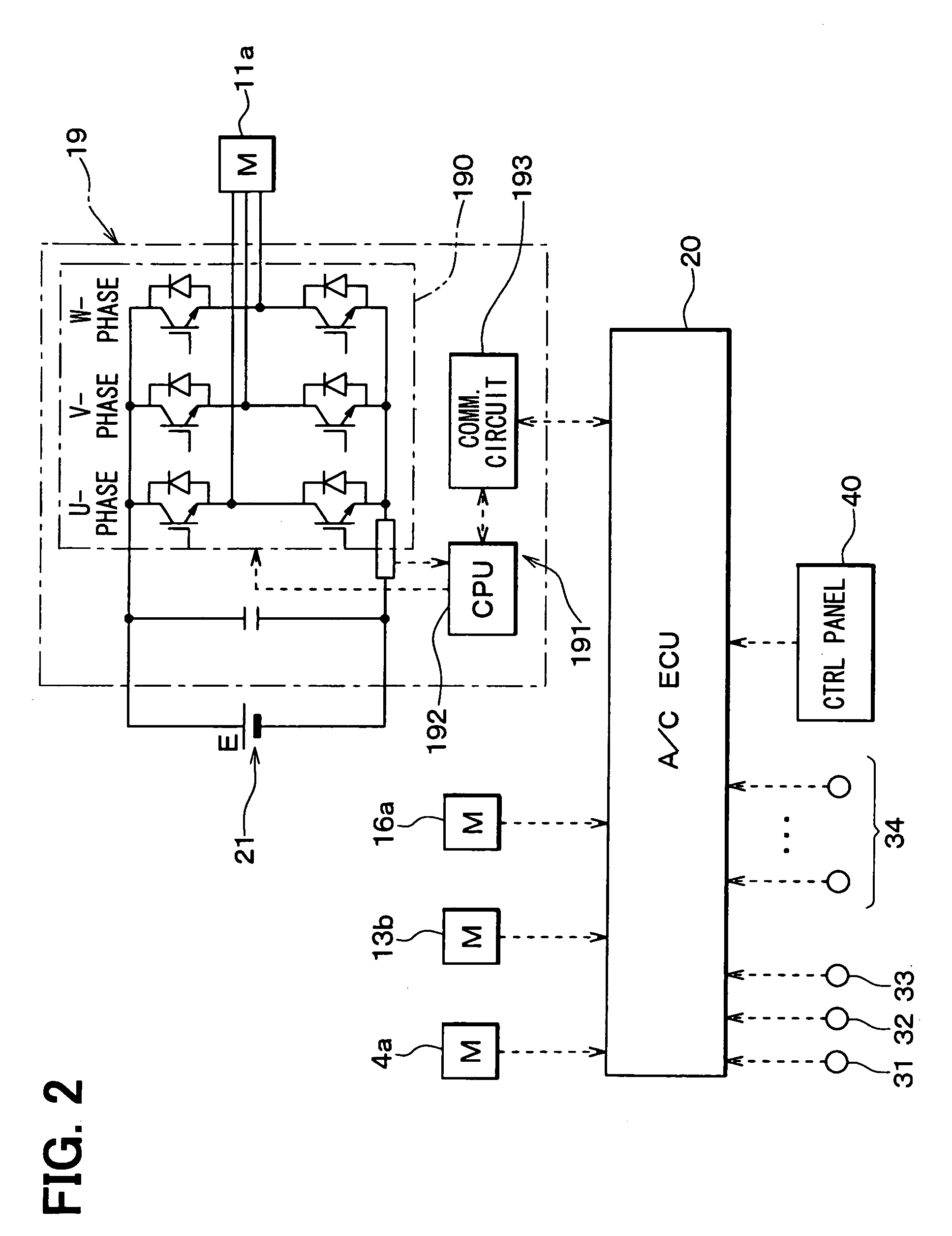
[0113]In the above-described second embodiment, a certain control characteristic is selected in accordance with the operation mode, and the temperature of the electric motor 11a is calculated and detected from the detection value of the inverter unit 19, on the basis of the selected control characteristic. In contrast, in the third embodiment, two or more control characteristics in which the criterion values are different are memorized beforehand in ROM etc. of the air conditioner controller 20. Then, a certain control characteristic is selected from the two or more control characteristics in accordance with a degree of superheat of the refrigerant at the suction side of the electric compressor 11, ...


PUM


Abstract

In a refrigerant cycle system, a compression mechanism of an electric compressor sucks and compresses refrigerant, and an electric motor that drives the compression mechanism is cooled by the refrigerant. A variable throttle mechanism decompresses the refrigerant discharged from the electric compressor. A motor temperature detector detects a temperature of the electric motor. A motor protection determiner determines whether the temperature of the electric motor detected by the motor temperature detector is equal to or higher than a criterion value. A motor protection controller controls the variable throttle mechanism so that an opening degree of the variable throttle mechanism does not decrease when the motor protection determiner determines that the temperature of the electric motor is equal to or higher than the criterion value.

Description

CROSS REFERENCE TO RELATED APPLICATION[0001]This application is based on and incorporates herein by reference Japanese Patent Application No. 2008-082749 filed on Mar. 27, 2008.BACKGROUND OF THE INVENTION[0002]1. Field of the Invention[0003]The present invention relates to a refrigerant cycle system having an electric compressor.[0004]2. Description of Related Art[0005]Conventionally, in an electric compressor in which a compression mechanism and an electric motor for driving the compression mechanism are integrated, a temperature protection control is performed as disclosed in JP2006-291878A and JP2005-248730A, for example. In order to avoid excessive temperature rise of the electric motor, the temperature protection control is performed when the temperature of an inverter, the electric motor, etc., excessively rises due to heavy load condition of the electric compressor.[0006]In JP2006-291878A, the temperature of the electric motor is evaluated on the basis of the motor speed of t...

Claims


Application Information

Patent Timeline
Patent Type & Authority Applications(United States)
IPC IPC(8): F25B41/00F25B1/06F25B31/00F04B35/04F25D17/06
CPCB60H1/3225B60H2001/3238B60H2001/3285B60H2001/3292F25B2700/21156F25B49/027F25B2600/2513F25B2700/171F25B49/005
Inventor KURIBAYASHI, NOBUKAZUKURODA, YASUTAKAOOMURA, MITSUYOMATSUNAGA, KENITOH, SATOSHI
Owner DENSO CORP
Why Eureka
Try Eureka