Preparation of a dense, polycrystalline ceramic structure

a technology of polycrystalline ceramics and dense powders, which is applied in the direction of turning machines, turning machine accessories, drawing profiling tools, etc., can solve the problem of grains much larger than those of the starting nanopowder

Inactive Publication Date: 2009-10-01
LOS ALAMOS NATIONAL SECURITY
View PDF6 Cites 4 Cited by
  • Summary
  • Abstract
  • Description
  • Claims
  • Application Information

AI Technical Summary

Problems solved by technology

All conventional sintering methods cause some grain growth that can

Method used


Image

  • Preparation of a dense, polycrystalline ceramic structure
  • Preparation of a dense, polycrystalline ceramic structure
  • Preparation of a dense, polycrystalline ceramic structure

Examples


Embodiment Construction

[0017]The invention involves producing a dense, crystalline, ceramic structure from ceramic powder. Preferably, the structures are nanocrystalline and are formed from ceramic nanopowder.

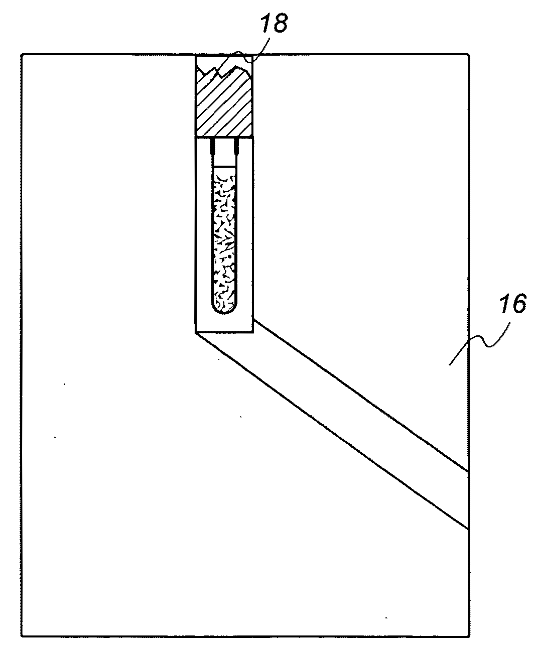
[0018]When the ceramic powder is nanopowder, the invention involves sealing an evacuated metal container with ceramic nanopowder inside and then forcing the sealed metal container through a severe deformation channel at an elevated temperature below the melting point of the ceramic nanopowder. The result is a dense nanocrystalline ceramic structure inside the metal container.

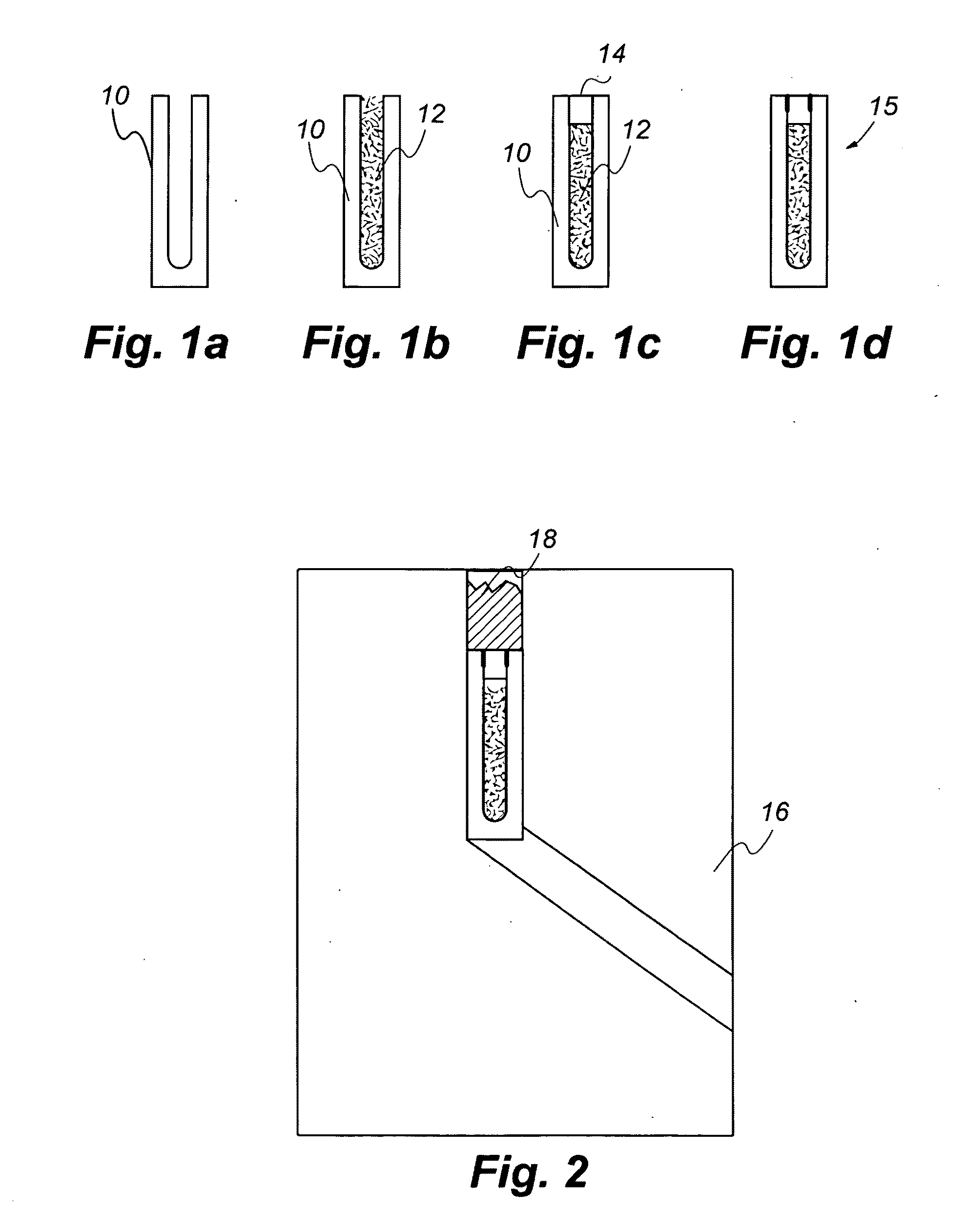
[0019]Reference will now be made in detail to embodiments of the invention. Similar or identical structure is identified using identical callouts. FIG. 1a-d show a series of sketches for preparation of the sealed container. FIG. 1a shows a sketch of the empty container 10. In a demonstration embodiment, the container was made of nickel and had an outer diameter of 10 mm and an inner diameter of 7 mm.

[0020]FIG. 1b shows container ...


PUM

PropertyMeasurementUnit
Temperatureaaaaaaaaaa
Structureaaaaaaaaaa
Melting pointaaaaaaaaaa

Abstract

Ceramic nanopowder was sealed inside a metal container under a vacuum. The sealed evacuated container was forced through a severe deformation channel at an elevated temperature below the melting point of the ceramic nanopowder. The result was a dense nanocrystalline ceramic structure inside the metal container.

Description

RELATED APPLICATIONS[0001]This application claims the benefit of U.S. Provisional Patent Application Ser. No. 61 / 072,684 entitled “DENSIFICATION OF CERAMICS VIA A SEVERE DEFORMATION PROCESS,” incorporated by reference herein.STATEMENT REGARDING FEDERAL RIGHTS[0002]This invention was made with government support under Contract No. DE-AC52-06NA25396 awarded by the U.S. Department of Energy. The government has certain rights in the invention.FIELD OF THE INVENTION[0003]The present invention relates generally to forming dense, polycrystalline, ceramic structures from ceramic powder.BACKGROUND OF THE INVENTION[0004]Nanocrystalline ceramic structures have a grain size of 100 nanometers (“nm”) or less. They can exhibit superior properties over their coarser polycrystalline (i.e. many grained) counterparts, and are attractive for many different areas including optical, microelectronic, magnetic, structural, thermal, electric, chemical, and refractory applications.[0005]Nanocrystalline ceram...

Claims


Application Information

Patent Timeline
IPC IPC(8): B28B1/00B29C47/00
CPCB21C23/001B21C23/002B28B3/025B28B3/24B82Y30/00C04B2235/604C04B35/645C04B2235/3227C04B2235/3229C04B2235/5454C04B35/5152
Inventor COOLEY, JASONCHEN, CHING-FONGALEXANDER, DAVID
Owner LOS ALAMOS NATIONAL SECURITY
Why Eureka
Try Eureka