X-ray Tube

a technology of x-ray tube and x-ray tube, which is applied in the direction of x-ray tube vessel/container, electrical discharge tube, electrical apparatus, etc., can solve the problems of maintenance problem, increase in facility cost, and problem with conventional x-ray tube shown in fig. 4

Inactive Publication Date: 2014-04-03
FUTABA CORPORATION +1
View PDF22 Cites 3 Cited by
  • Summary
  • Abstract
  • Description
  • Claims
  • Application Information

AI Technical Summary

Benefits of technology

[0011]The X-rays are radiated through the X-ray transmission window 54 which is limited by the opening portion 52 of the substrate 53. Thus, by setting the size of the elongated slit of the opening portion 52 to a desired size, the radiation region of the X-ray can be substantially linear so that the X-rays can spread with a slit width of the X-ray transmission window 54. Thus, the irradiation area which is effectively large with respective to the size of the subject can be set easily with a relatively high degree of freedom, thereby providing advantageous effect which cannot be obtained from the circular X-ray tube having the narrow irradiation area. Furthermore, by setting the size and shape of the opening portion 52 to a rectangular slot-like shape having a desired size, it is possible to determine the radiation region of the X-rays on the X-ray transmission window 54 from the appearance more easily than the circular X-ray transmission window, thus it is relatively easy to set a path for accurately directing the X-rays to a desired location.
[0017]The present invention is based on the above-described new problem which was found by analyzing the phenomenon discovered by the inventors of the present invention. Thus, an object of the present invention is to provide a flat X-ray tube which includes an electron source, a control electrode and an X-ray target and such arranged inside of a package in a high-vacuum state and which prevents a change in X-ray intensity with time.
[0019]Furthermore, the present invention provides, in a second aspect, the X-ray tube described above, wherein the shielding electrode is provided in a pair so as to sandwich the window portion, such that electrons collided with the X-ray target and reflected are prevented from reaching to an inner surface of the container portion and that discharge between the shielding electrode and the second control electrode is prevented, and wherein a distance between each of the shielding electrodes and the second control electrode is set such that an electric field formed between the shielding electrodes and the second control electrode at an operating voltage does not exceed a discharge electric field threshold of 10 kV / mm.
[0020]As explained above, according to the X-ray tube described in the first aspect, the electrons drawn from the electron source by action of the first control electrode are collided with the X-ray target within the irradiation area defined by the second control electrode. As a result, X-rays are generated from the X-ray target are radiated to outside through the X-ray transmission window. At the same time, some of the electrons collided with the X-ray target are reflected, and some of these reflected electrons travel toward the inner surface of the container portion and such if no measure is taken. However, since the X-ray tube is provided with the shielding electrode arranged on the inner surface of the substrate along the slit-like window portion having the X-ray target with which the electrons collide, the electrons reflected on the X-ray target between the shielding electrodes are absorbed by the shielding electrodes and become a part of the X-ray target current, so the electrons will not reach to the inner surface of the container portion and such. As a result, even if the X-ray tube is continuously operated, the emission of electrons from the electron source will not be unstable with time, preventing the above-mentioned current degradation and the current increase. In other words, regardless of time, the target current can be stabilized, and the X-rays of constant and uniform intensity can be radiated at all times.

Problems solved by technology

However, the conventional X-ray tube shown in FIG. 4 has a problem as described below.
Therefore, when using such circular X-ray tube having the narrow irradiation area, it is necessary to use many X-ray tubes arranged next to each other to irradiate a wide region with the X-ray, causing an increase in the facility cost and causing a maintenance problem.
In this case, however, it is necessary to increase the irradiation intensity to irradiate the irradiation subject with desired X-rays, and also, other undesired area may be irradiated, causing a leak of X-rays.

Method used


Image

  • X-ray Tube
  • X-ray Tube
  • X-ray Tube

Examples


Embodiment Construction

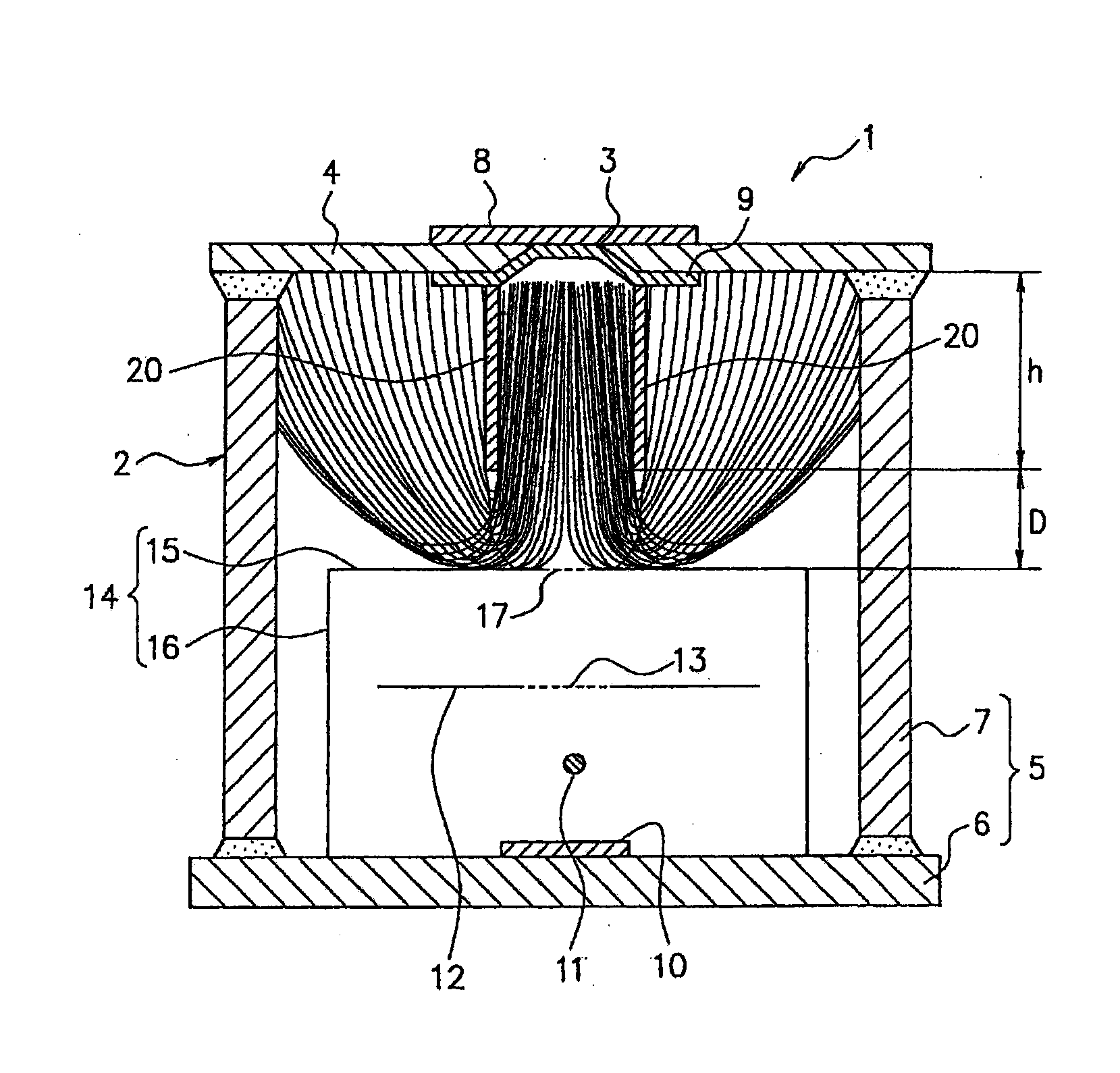
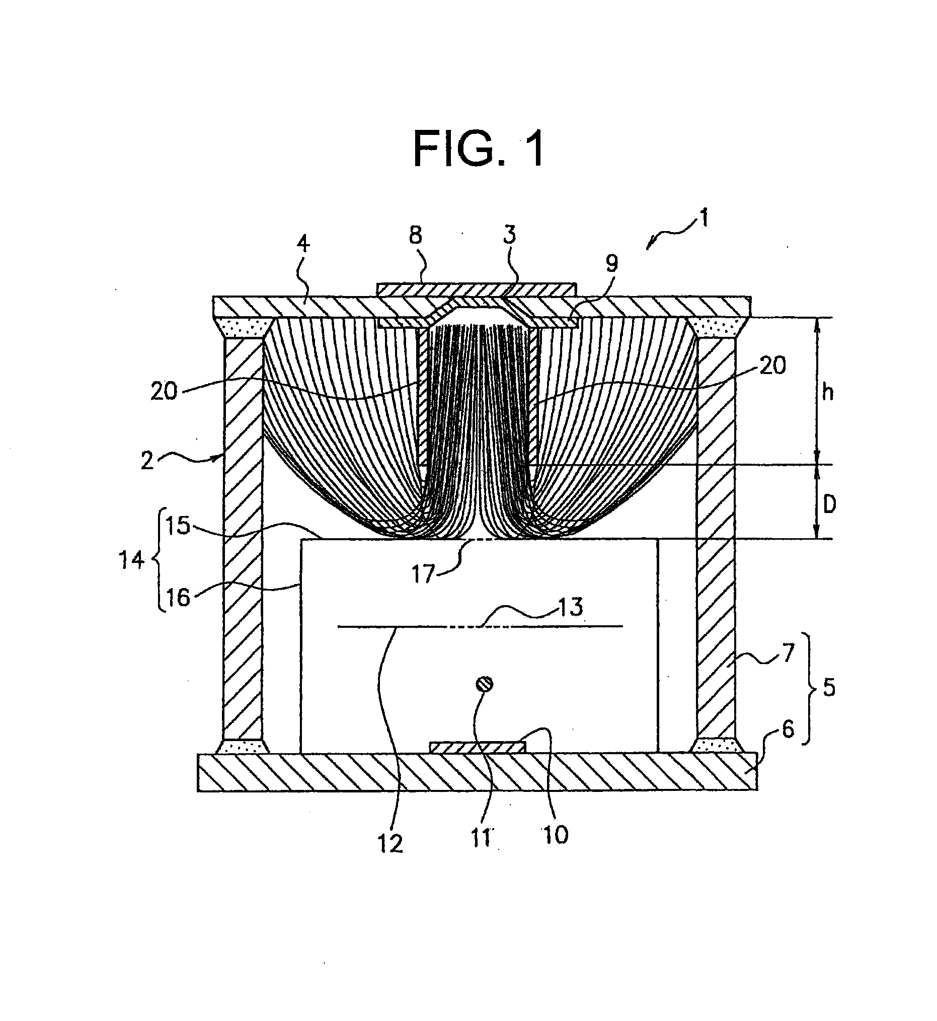
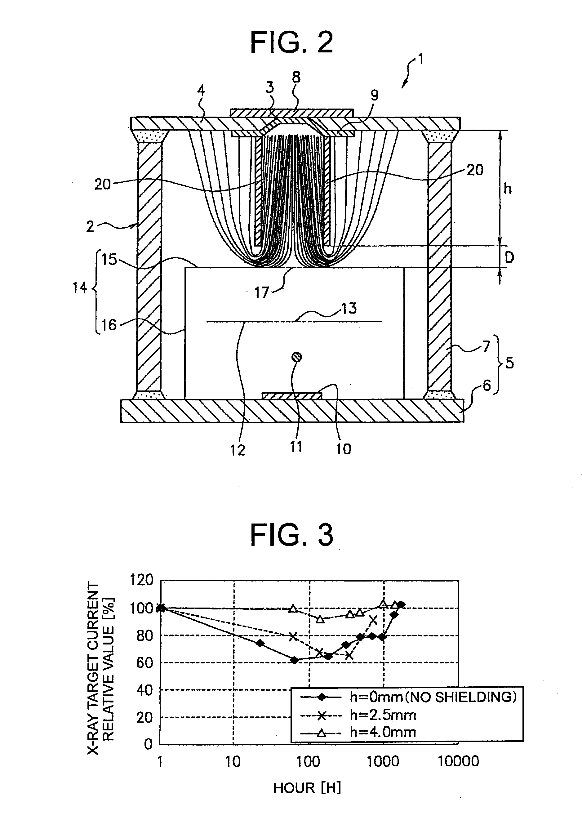
[0032]In the following, a first embodiment of the present invention is explained in reference to FIGS. 1 to 3. An X-ray tube shown in FIG. 1 and an X-ray tube shown in FIG. 2 have the same structure except for a later-described shielding electrode. The shielding electrode of FIG. 1 and the shielding electrode of FIG. 2 are different in size. FIG. 1 and FIG. 2 show trajectories of reflected electrons obtained from a simulation by an analysis of electric field using a finite element method. FIG. 3 is a graph showing a relationship between operating time and an X-ray target relative current for X-ray tubes of the above-described two examples of the first embodiment and for an old model conventional X-ray tube developed by the inventors of the present invention.

[0033]An X-ray tube 1 according to the first embodiment shown in FIG. 1 and FIG. 2 is a flat-tube-type and includes a box-like package 2 as a main body. This package 2 includes a radiopaque substrate 4 provided with a window port...


PUM


Abstract

An X-ray tube includes a radiopaque substrate including a window portion, an X-ray transmission window closing the window portion, an X-ray target provided at the window portion from an inner surface side of the substrate, a highly-evacuated container portion attached to the inner surface of the substrate, a cathode, a first control electrode and a second control electrode provided inside the container portion. A shielding electrode is provided at the inner surface of the substrate so as to surround the window portion. Electrons collide with the X-ray target to generate X-rays. Electrons reflected on the X-ray target between the shielding electrodes are absorbed by the shielding electrodes, so an inner surface of the container portion is not charged. The electron emission from the cathode is not affected by the reflected electrons, so a change in target current is small, and thus X-rays of substantially constant intensity can be radiated.

Description

CROSS-REFERENCE TO RELATED APPLICATION[0001]This application claims priority from Japanese Patent Application No. 2012-220583 filed on Oct. 2, 2012, the contents of which are hereby incorporated by reference.TECHNICAL FIELD[0002]The present invention relates to an X-ray tube arranged to emit electrons from an electron source located on an inside of a package in a high-vacuum state, make the electrons collide with an X-ray target and radiate X-rays emitted from the X-ray target to outside through an X-ray transmission window. More specifically, the present invention relates to the X-ray tube which can prevent destabilization of operating characteristics caused by scattering, in the package, of the electrons which were reflected at the X-ray target.BACKGROUND ART[0003]Patent Literature 1 mentioned below discloses an X-ray generator for generating ion gas by irradiating air with X-rays. An X-ray tube used in this X-ray generator includes a main body which is a cylindrical package (or b...

Claims


Application Information

Patent Timeline
Patent Type & Authority Applications(United States)
IPC IPC(8): H01J35/18
CPCH01J35/18H01J35/16H01J2235/168H01J35/116H05G1/06
Inventor MATSUMOTO, AKIRADEGUCHI, KIYOYUKIMARUSHIMA, YOSHIHISAKOGURE, YUUICHINAKAMURA, KAZUHITOOKADA, TOMOYUKIFUJITA, TORUNAKAMURA, TATSUYA
Owner FUTABA CORPORATION
Why Eureka
Try Eureka