Method of controlling fuel cell vehicle and method of controlling dc/dc converter apparatus

a fuel cell vehicle and converter technology, applied in the direction of electric energy management, gas pressure propulsion mounting, electric devices, etc., can solve the problems of heat generation concentration in such a switching device, and achieve the effects of avoiding heat generation concentration, simple design, and convenient transition

Inactive Publication Date: 2009-10-01
HONDA MOTOR CO LTD
View PDF14 Cites 18 Cited by
  • Summary
  • Abstract
  • Description
  • Claims
  • Application Information

AI Technical Summary

Benefits of technology

[0021]The method may further comprise the step of, during the direct couple control, outputting the drive signals to the switching devices in a fixed order. This allows the heat release period of each switching device to be dispersed, and the concentration of heat generation can be avoided.
[0022]The DC / DC converter may be capable of performing voltage-increasing and voltage-decreasing operations, and the controller may be capable of executing voltage-increasing control and voltage-decreasing control that cause the DC / DC converter to perform the voltage-increasing operation and the voltage-decreasing operation, respectively. The method may further comprise the step of outputting, by the controller, the drive signals to the switching devices in the same order during each of the voltage-increasing control, the voltage-decreasing control, and the direct couple control. In this case, the voltage-increasing chopper control, voltage-decreasing chopper control, and direct couple control have a commonality, which facilitates transition from the voltage-increasing or voltage-decreasing chopper control to the direct couple control, and vice versa.
[0023]The method may further comprise the step of during the direct couple control, simultaneously with stopping output of the drive signal to one switching device, starting output of the drive signal to another switching device. This allows smooth flow of current when switching between the switching devices.
[0024]Preferably, the plurality of switching devices is fixed on a common heat sink. This allows a simple design for heat release.
[0025]Preferably, the DC / DC converter apparatus may further include temperature sensors for measuring temperatures of the plurality of switching devices. The method may further comprise the step of, by the controller, stopping operation of a switching device having a temperature higher than a predetermined threshold and causing a switching device having a temperature lower than the predetermined threshold to operate. In this way, the operation of the switching device having a temperature above the predetermined threshold can be stopped while maintaining the direct couple control. Hence, the reliability of the DC / DC converter apparatus can be improved.
[0026]The first electric power device may be a power storage device and the second electric power device may be a power generating device, and, the method may further comprise the step of, during the direct couple control, charging the power storage device with power generated by the power generating device. In this configuration, since, in the direct control, the drive signals are inputted to the switching devices intermittently on a one switching cycle basis, the heat generation of the switching device can be reduced. Hence, heat generated by the current flowing from the power generating device to the power storage device for charging the power storage device can be prevented from damaging the switching devices. Therefore, interruption of charging the power storage device by the power generating device due to the damage of the switching device can be prevented, and the power storage device can be charged satisfactorily.

Problems solved by technology

If the drive signals causing no voltage conversion are continuously inputted to all switching devices, larger current flows in the switching device having a lower on-resistance, resulting in concentration of heat generation in such a switching device.

Method used


Image

  • Method of controlling fuel cell vehicle and method of controlling dc/dc converter apparatus
  • Method of controlling fuel cell vehicle and method of controlling dc/dc converter apparatus
  • Method of controlling fuel cell vehicle and method of controlling dc/dc converter apparatus

Examples


embodiment

A. Embodiment

[0045]Hereinafter, a fuel cell vehicle equipped with an embodiment of a DC / DC converter apparatus according to the present invention will be described, with reference to the accompanying drawings.

1. Configuration of Fuel Cell Vehicle 20

(1) General Configuration

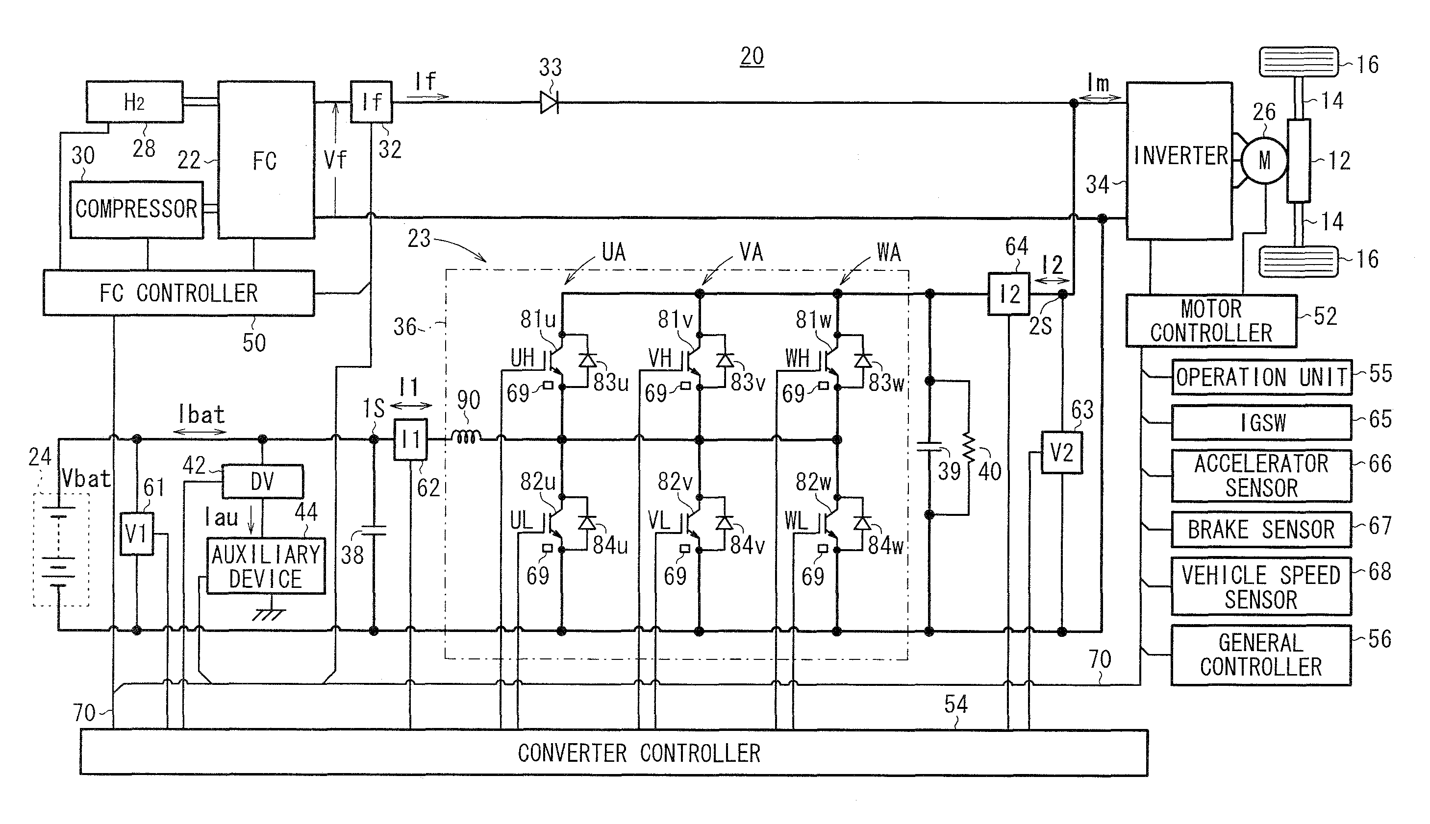
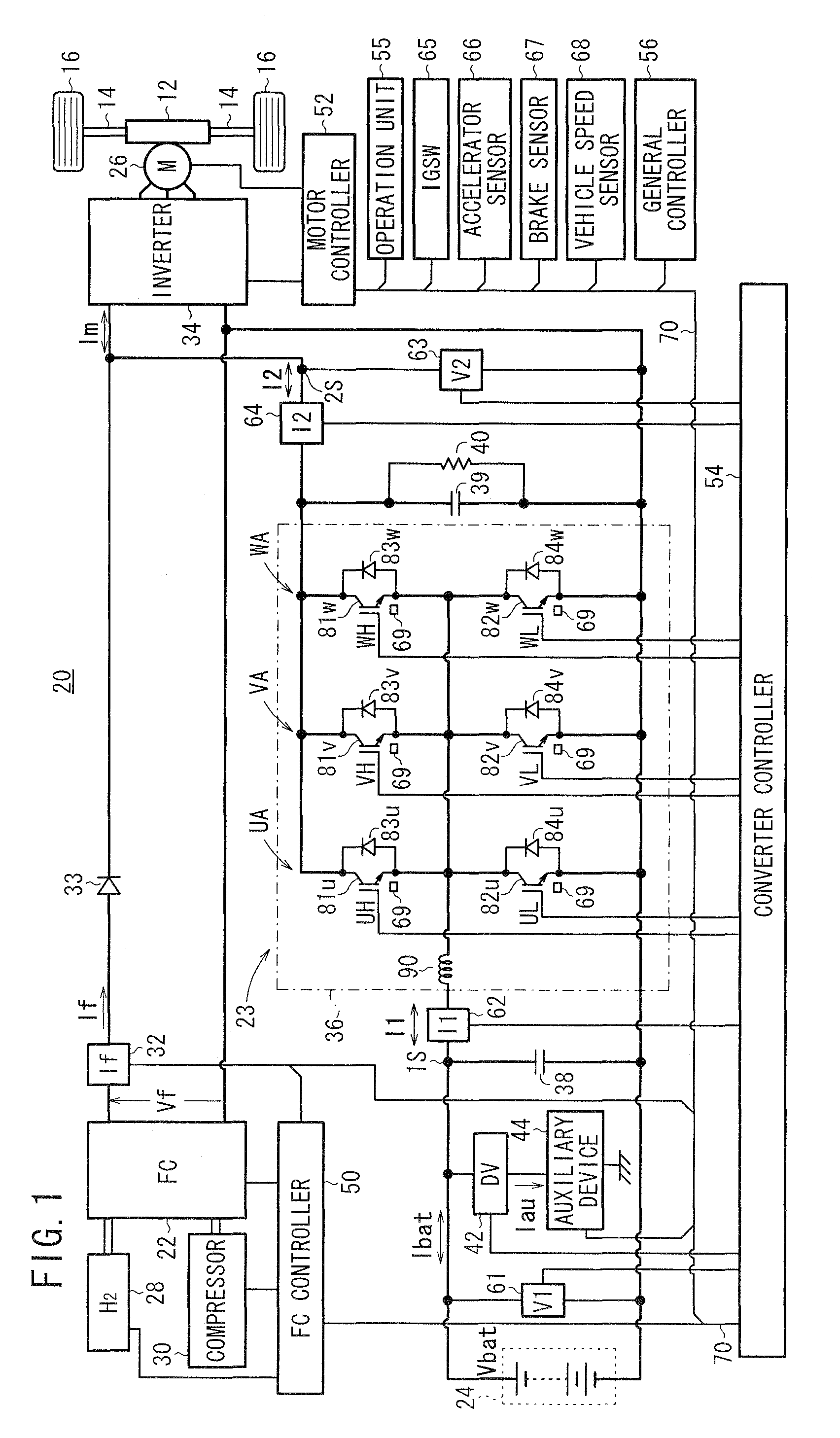
[0046]FIG. 1 is a circuit diagram of the fuel cell vehicle 20 equipped with a DC / DC converter apparatus 23 according to the present embodiment. The fuel cell vehicle 20 basically includes a hybrid electric power device, a travel motor 26, and a DC / DC converter apparatus (also referred to as a “VCU (Voltage Control Unit)”) 23. The hybrid electric power supply device is made up of a fuel cell 22 and a power storage device 24 (referred to as a “battery”). The power storage device 24 serves as an energy storage. The travel motor 26 is supplied with current (electrical power) from the hybrid electric power supply device via an inverter 34. The DC / DC converter apparatus 23 has a primary side 1S connected to the battery ...


PUM


Abstract

A controller is capable of executing direct couple control that directly couples a first power device and a second power device without causing a DC/DC converter to convert voltage. During the direct couple control, a drive signal that causes no voltage conversion is intermittently output to at least one of a plurality of switching devices.

Description

BACKGROUND OF THE INVENTION[0001]1. Field of the Invention[0002]The present invention relates to a method of controlling a fuel cell vehicle and a method of a DC / DC converter apparatus, the fuel cell vehicle and the DC / DC converter apparatus including a DC / DC converter having a plurality of switching devices connected in parallel between two electric power devices (e.g. a fuel cell and a power storage device), and a controller for controlling voltage conversion performed by the DC / DC converter. More particularly, the present invention relates to a method of controlling a fuel cell vehicle and a method of controlling a DC / DC converter apparatus, in which the controller can execute direct couple control that directly couples the two electric power devices without voltage conversion being performed by the DC / DC converter.[0003]2. Description of the Related Art[0004]There has been known a DC / DC converter apparatus which performs voltage-increasing and voltage-decreasing processes using ...

Claims


Application Information

Patent Timeline
Patent Type & Authority Applications(United States)
IPC IPC(8): B60L1/00
CPCB60L11/12B60L11/1887B60L2210/10H02M3/1584Y10S903/907Y02T10/7216Y02T90/34H02M2003/1586Y02T10/7077B60L50/15B60L58/40H02M3/1586Y02T10/70Y02T10/7072Y02T10/72Y02T90/40
Inventor MIMATSU, NAOYUKIKOJIMA, YASUSHIMURASHIGE, SEIGOASANO, YUTAKA
Owner HONDA MOTOR CO LTD
Why Eureka
Try Eureka