
Method of fully charging an electrical energy storage device using a lower voltage fuel cell system

Inactive Publication Date: 2009-10-01
GM GLOBAL TECH OPERATIONS LLC
View PDF15 Cites 15 Cited by
  • Summary
  • Abstract
  • Description
  • Claims
  • Application Information

AI Technical Summary

Benefits of technology

[0012]In accordance with the teachings of the present invention, a fuel cell system is disclosed that includes a fuel cell stack and an EESD electrically coupled to a common high voltage bus line. The EESD has a higher voltage output than the fuel cell stack, and thus the stack is unable to fully charge the EESD, for example, at system shut-down. In order to allow the fuel cell stack to fully charge the EESD, the EESD is separated into a plurality of separate electrical storage

Problems solved by technology

The EESD has a higher voltage output than the fuel cell stack, and thus the stack is unable to fully charge the EESD, for example, at system shut-down.

Method used


Image

  • Method of fully charging an electrical energy storage device using a lower voltage fuel cell system
  • Method of fully charging an electrical energy storage device using a lower voltage fuel cell system
  • Method of fully charging an electrical energy storage device using a lower voltage fuel cell system

Examples


Embodiment Construction

[0017]The following discussion of the embodiments of the invention directed to a fuel cell system including a fuel cell stack and an EESD separated into a plurality of storage banks is merely exemplarary in nature, and is in no way intended to limit the invention or its applications or uses.

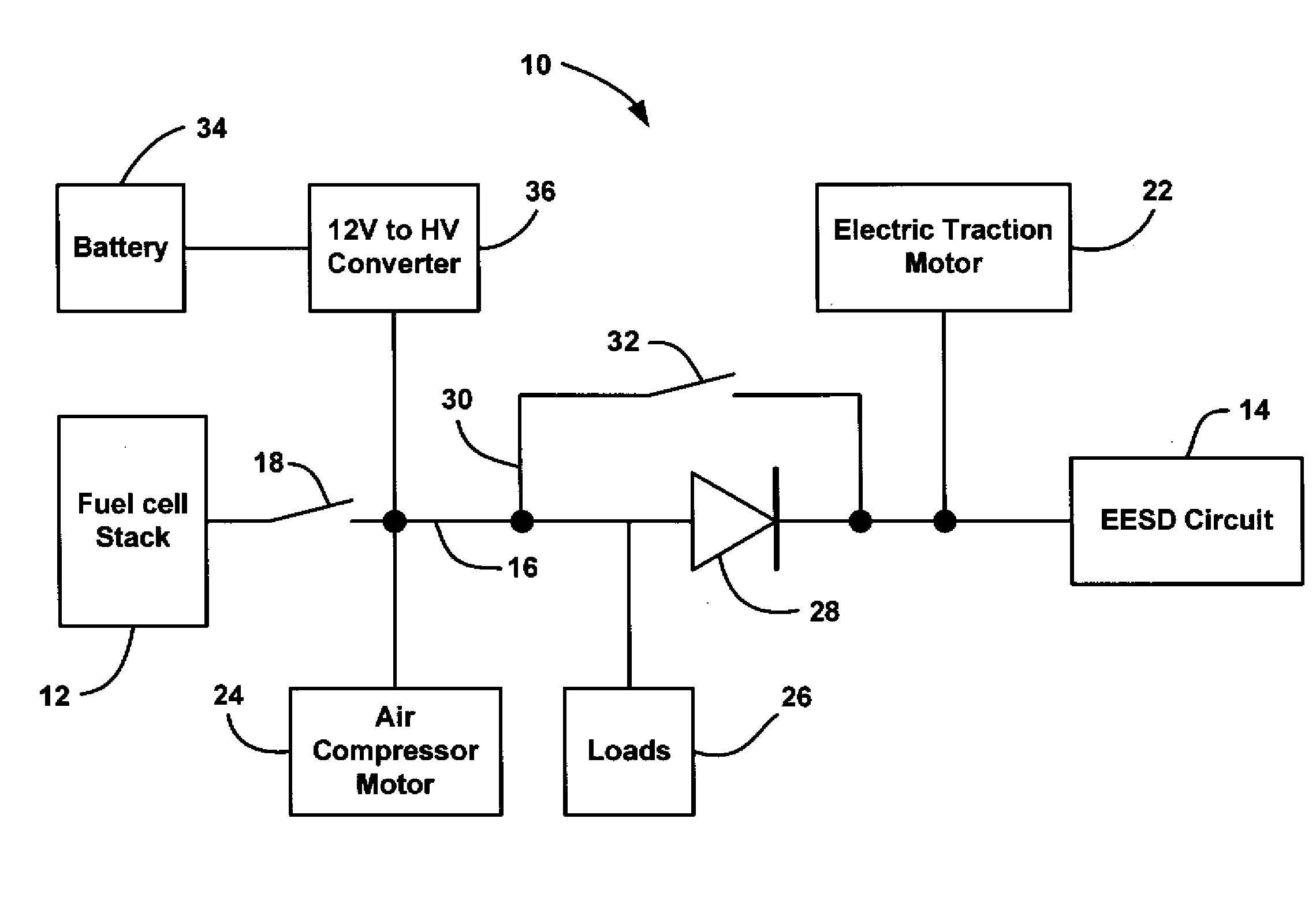
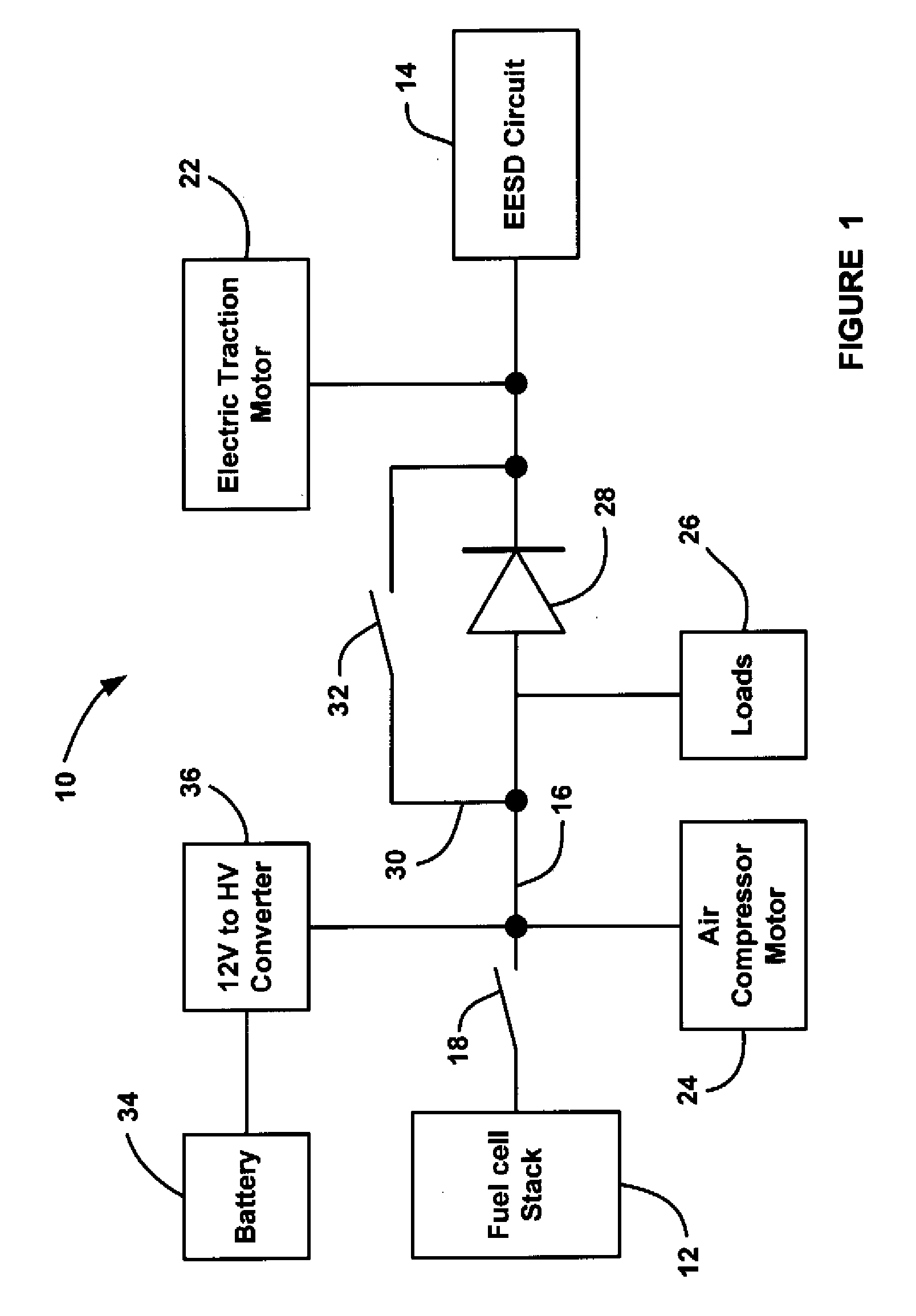
[0018]FIG. 1 is a schematic block diagram of a fuel cell system 10 including a fuel cell stack 12 and an EESD circuit 14 both electrically coupled to a high voltage bus line 16. As will be discussed in detail below, the EESD circuit 14 includes more than one storage bank. The EESD circuit 14 can employ any suitable DC power source for the purposes described herein, such as a battery, an ultracapacitor, a super-capacitor, etc. A fuel cell stack switch 18 selectively connects and disconnects the fuel cell stack 12 to the high voltage bus line 16. Various electrical components are electrically coupled to the high voltage bus line 16, such as an electric traction motor 22 that propels the vehicle. Ad...


PUM


Abstract

A fuel cell system that includes a fuel cell stack and an EESD electrically coupled to a common high voltage bus line. The EESD has a higher voltage output than the fuel cell stack, and thus the stack is unable to fully charge the EESD, for example, at system shut-down. In order to allow the fuel cell stack to fully charge the EESD, the EESD is separated into a plurality of separate electrical storage banks having lower voltage potentials. A series of contactors are provided to electrically couple the storage banks in series during normal system operation, and separately charge the storage banks using the fuel cell stack so that they are fully charged. The series of contactors can also be configured so that the storage banks can be electrically coupled in series during normal operation of the system and be electrically coupled in parallel during charging at system shut-down.

Description

BACKGROUND OF THE INVENTION[0001]1. Field of the Invention[0002]This invention relates generally to a fuel cell system including a fuel cell stack and an electrical energy storage device and, more particularly, to a fuel cell system including a fuel cell stack and an electrical energy storage device where the electrical energy storage device is separated into more than one storage bank so that the fuel cell stack has a high enough voltage to charge the electrical energy storage device.[0003]2. Discussion of the Related Art[0004]Hydrogen is a very attractive fuel because it is clean and can be used to efficiently produce electricity in a fuel cell. A hydrogen fuel cell is an electrochemical device that includes an anode and a cathode with an electrolyte therebetween. The anode receives hydrogen gas and the cathode receives oxygen or air. The hydrogen gas is dissociated in the anode to generate free hydrogen protons and electrons. The hydrogen protons pass through the electrolyte to t...

Claims


Application Information

Patent Timeline
IPC IPC(8): H01M10/44H02J7/00H01M8/04
CPCB60L11/1887Y02T90/34H01M16/006H01M10/46B60L58/40Y02E60/10Y02E60/50Y02T10/70Y10S903/908Y02T90/40
Inventor WHITEHOUSE, KRISTIAN M.KEYES, DAVID JOHNFERRERO, JOSEPH J.
Owner GM GLOBAL TECH OPERATIONS LLC
Learn More