
Fundus camera

a camera and fundus technology, applied in the field offundus cameras, can solve the problems of limited degree of freedom of optical engineering, difficult observation to be performed, and difficult for a photographer to judge the cause of blurred fundus images and take measures against blurred fundus images. achieve the effect of favorable performan

Inactive Publication Date: 2009-10-01
NIDEK CO LTD
View PDF2 Cites 35 Cited by
  • Summary
  • Abstract
  • Description
  • Claims
  • Application Information

AI Technical Summary

Benefits of technology

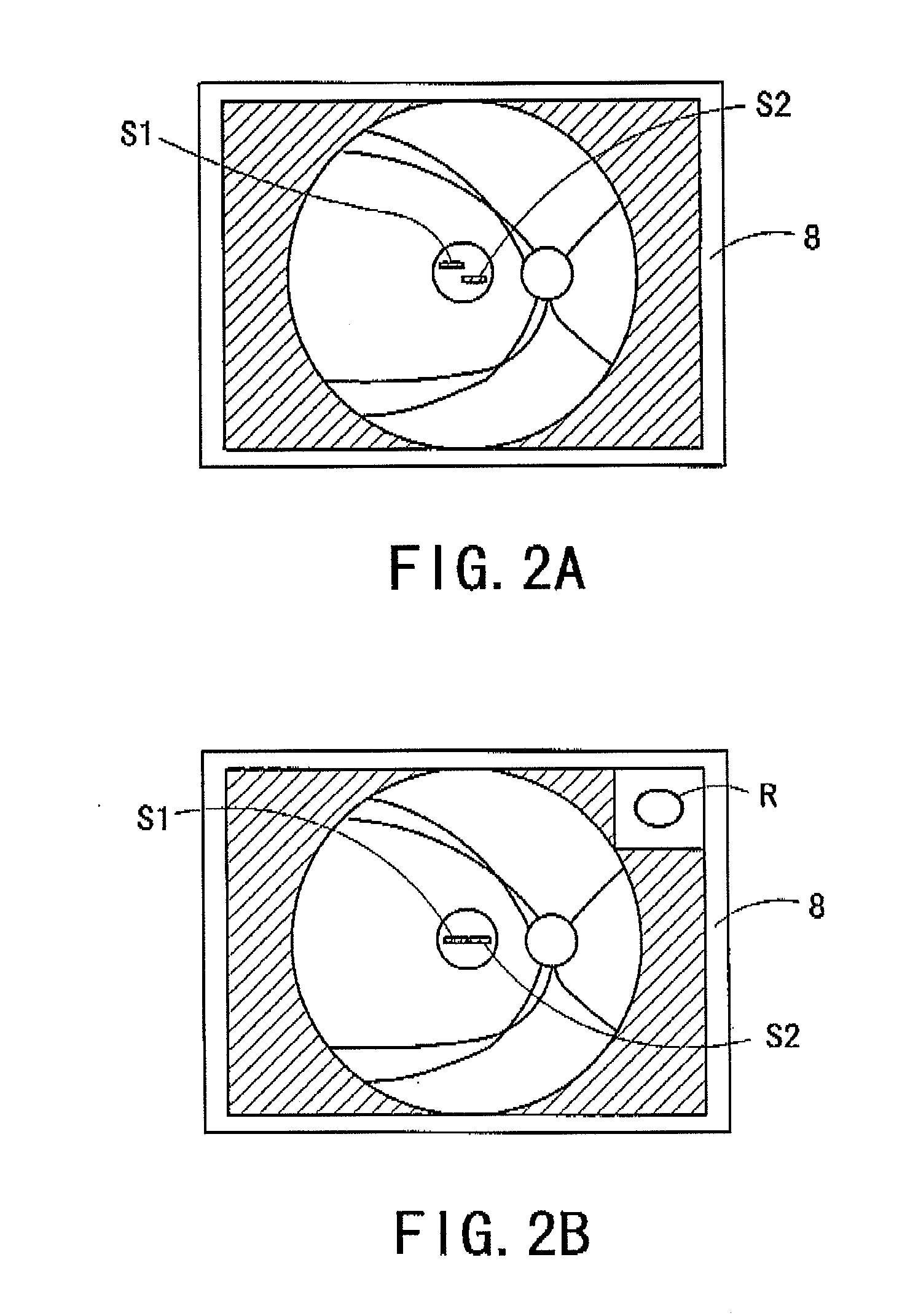
[0009]An object of the invention is to overcome the first problem described above and to provide a fundus camera capable of favorably performing focusing on a fundus of an examinee's eye without being provided with a black dot plate in an optical system for projecting focus targets. Another object of the invention is to overcome the second problem described above and to provide a fundus camera by which a state of an examinee's eye is easily known during photographing.

Problems solved by technology

In such a case, there is a first problem that the degree of freedom of optical engineering is limited.
This brings about a second problem that when a fundus of an eye with severe myopic is photographed, an image of the fundus is blurred even though the photographing is performed with the fundus in focus, and accordingly observation could be difficult to perform.
It is difficult for a photographer to judge the cause of the blurred fundus image and take measures against the blurred fundus image.

Method used


Image

  • Fundus camera
  • Fundus camera
  • Fundus camera

Examples


Embodiment Construction

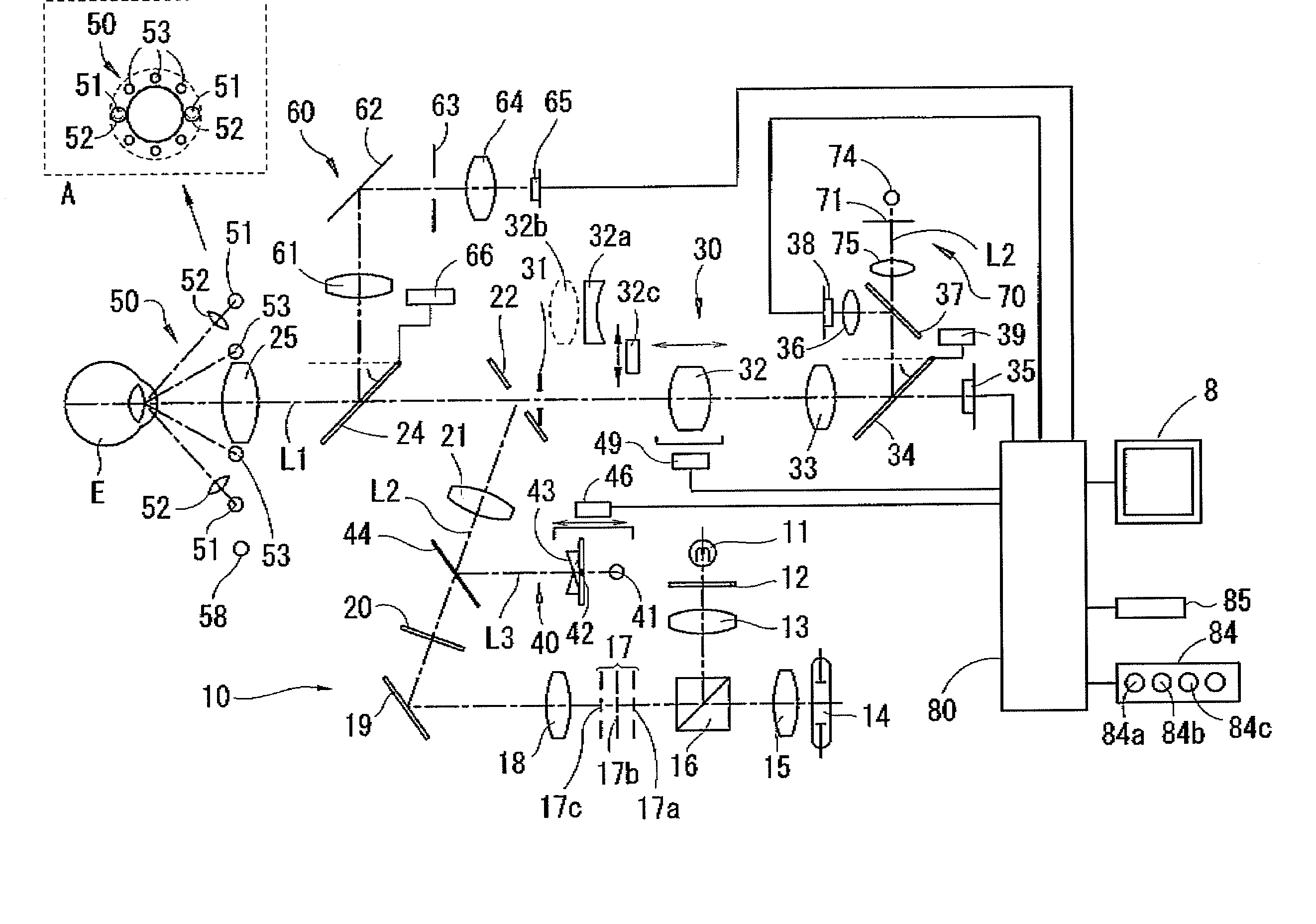
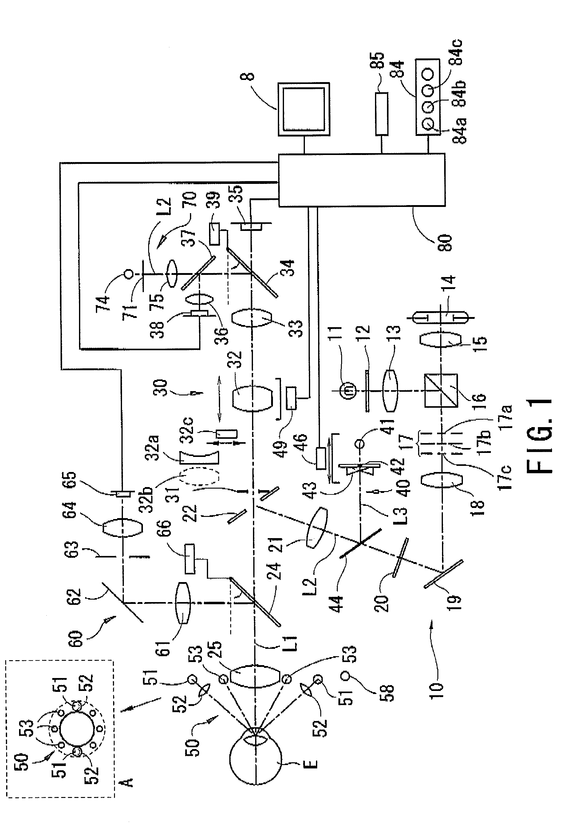
[0029]A detailed description of preferred embodiments of a fundus camera embodied by the present invention is provided below with reference to the accompanying drawings. FIG. 1 is a schematic view showing an optical system and a control system of a fundus camera according to a first preferred embodiment of the present invention. The optical system comprises an illumination optical system 10, a fundus observation / photographing optical system 30, a focus target projection optical system 40, an alignment target projection optical system 50, an anterior-segment observation optical system 60, and a fixation target presenting optical system 70.

Illumination Optical System 10

[0030]The illumination optical system 10 comprises an observation illumination optical system and a photographing illumination optical system. The photographing illumination optical system comprises a photographing light source 14 such as a flash lamp, a condenser lens 15, a first shielding plate 17a having a circular s...


PUM


Abstract

A fundus camera favorably performing focusing on a fundus of an examinee's eye without a black dot plate in a target projection optical system comprises an illumination optical system comprising a light source and an objective lens, a photographing optical system comprising a focusing lens movable in the optical axis direction and a diopter correction lens to correct a diopter of severe ametropia, a first moving mechanism comprising a first driving unit moving the focusing lens, a focus detection optical system comprising a projection optical system comprising a light source and a photo-receiving optical system comprising a photodetector, a second moving mechanism comprising a second driving unit moving a part of the detection optical system including at least one of the projection light source and the photodetector in the optical axis direction, a monitor, and a control unit controlling the second unit in conjunction with movement of the focusing lens.

Description

BACKGROUND OF THE INVENTION[0001]1. Field of the Invention[0002]The present invention relates to a fundus camera which photographs a fundus of an examinee's eye.[0003]2. Description of Related Art[0004]Conventionally, a fundus camera which photographs a fundus of an examinee's eye comprises a focusing lens which is movable in an optical axis direction and is placed in a photographing optical path of a photographing optical system in order to perform focusing on the fundus. In addition, the fundus camera comprises an optical system for projecting light of split targets onto the fundus via a spot mirror attached to a focus lever which is inserted into and removed from an optical path of a fundus illumination optical system, and photo-receiving the light of the split targets reflected from the fundus by an image pickup element of a fundus observation optical system. An examiner grasps a focus deviation based on a separation state between images of the split targets (focus targets) when...

Claims


Application Information

Patent Timeline
Patent Type & Authority Applications(United States)
IPC IPC(8): A61B3/14
CPCA61B3/14
Inventor YOSHINO, MASAYUKIMIMURA, YOSHIAKITAWADA, AKIRAICHIKAWA, NAOKI
Owner NIDEK CO LTD
Learn More